"Decoding" an existing DCC installation in an LGB 23450

Software Tools

Registered
Country flag
I recently bought a LGB 23450 Green Ge 2/4. The price was very attractive so I expected there may be some issues but 23450s are hard to come by and I was prepared to have do some work on it. It was advertised as having a decoder fitted and running reliably.

It arrived in great physical condition but when put on a DC track would barely move. It took a while to start and would keep moving for a while when power was shut off, so it seemed likely it had a power buffer fitted.

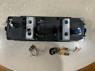
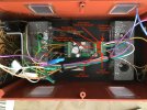
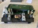
On opening it up, I found this.....
5B723F5B-A9C4-4961-96ED-BAFAB747D857.jpeg

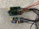
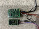
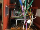
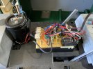
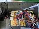
It appears that there is a fairly basic decoder in there with a bunch of stuff added around it. Here's a couple of close ups....
9DCB5F8E-3668-4015-B5C9-F275509B4E0F.jpeg

B7AE058A-74D1-40B7-8FDF-E1444723A971.jpeg

Now, my Massoth DCC kit still isn't installed (due to a bunch of other distractions), so I do not have the wherewithal to "look" at the contents of the decoder, but this whole set up looks so dodgy that I have already ordered a Massoth XLS that I can install myself, with an understanding of exactly what was done.

I'm hoping I can retrieve the decoder from under all the wiring and use it again later, as well as reuse the "stay alive" capacitor with the XLS, but right now I am interested in gaining some understanding of what was done here by the original installer, as well as what they might have been hoping to achieve.

I can see an additional bridge rectifier in there and what looks like a DIP relay but what purpose they serve in unclear. Any ideas?
 
Last edited:
I think I would be very tempted to bin the lot, it looks loke it may be very dodgy and could possibly trash your Massoth set up. Is it worth the risk?
 
It looks like it might be an arduino(sp) based board?
First thing:
Watch your fingers around the tags on that capacitor. - A length of tape, over the top, would be a good idea.

Bridge rectifier will give you a constant polarity DC voltage to drive the electronics.
Relay will give you forward/reverse to the motor.

Reason it was slow to start may be a setting within the decoder. Or, more likely, it needind some time and oomph to charge that capacitor.

If you are not sure, and have not followed the threads on power-buffers, then I agree with Jon..
Rip it out and start again..

PhilP.
 
I see a home-made keep-alive system... the big capacitor with the inrush resistor and the bypass diode soldered to it make that a certainty.

What makes you say it is DCC? If it is, that square board must be it, so maybe you could pull it up and look for markings.

It looks more to me that someone made a DC setup with a keepalive power supply and relays to get the sound to go before the motor.

I'd remove it all.

Greg
 
Life's to short...bin it...
Fresh start, at least you know its right then
 
Good grief what a messy job! Bin it.
 
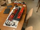
So, I've pulled the jury rig apart, and bridged the 4 pin motor connections for a DC test and the mechanism is working well.

E3847D42-2C8C-41D4-8122-EE5252B9BA25.jpeg

Underneath that rats-nest of wire, what I thought was a single decoder board in fact turned out to be two boards. Neither has any branding or identification on it but I am hoping somebody may recognise them.

209BFABB-207E-4246-8F78-90B103DDC763.jpeg
612C94F7-6F9D-4498-8D53-A429026FA1FF.jpeg

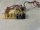
The small black box that was on the baseplate does indeed seem to be a bistable relay and appears to be wired to change the headlights around, depending on the polarity of the voltage applied to the motor.... very much in the manner of the way LGB handled the headlight switching on the early 2040 (Crocodile) locos.

AC3595EB-9689-420F-8A1A-7B4136ACA383.jpeg
 
Very odd that it appears to have a SUSI sound chip (as mentioned earlier, probably a Dietz or Uhlenbrock, which are "badge engineered" versions of the same thing), but no speaker anywhere....?

If the sound chip works, it would be worth re-using it in something else.

I'm wondering if the rather Heath Robinson looking relay setup for the lights is to do with the function current output from the Lenz driving decoder - with only 0.2 A available at each function output that may not have been enough to run all the lights on the loco?

Jon.
 
Has anyone actually done a bare bone up DCC installation on a LGB 23450? I've fitted other sorts of decoders to LGB locos in the past, but have always had the existing LGB analogue electronics available to work with (minimal as it may have been in some cases), so this will be a new experience for me.

I looked at the Ge 2/4 conversion info on the Massoth web site and it basically covers the LGB 22450 model which came with a LGB 10 pole interface. It also mentions "The LED illumination is supplied from [the] analogue PCB, so there is no change of decoder voltage needed."

Since there is nothing left from the original analogue electronics in my specific 23450, I am after some more advice. I'm assuming that I can plug the lighting cables directly into the Massoth 8230045 XLS, but that I may also need to do something about the setting the lighting voltage, which I gather can be done through the appropriate CVs. Is there likely to be anything else that needs to be done to compensate for the lack of the original LGB analogue electronics.

I've just received advice from GrootSpoor that my order for Massoth decoders has shipped, which has started my thinking about fitting one to this loco.
 
In some ways, it will be easier..
Do NOT initially connect the lights!
Do the install in stages..

1. Track and motors. - Proves the decoder, and motors, are good.
2. Speaker, and if fitting, volume control. - Proves sound functions.
You can also connect chuff-sensors, and Reed switches, at this point..
3. Lights....
You say these are LEDs, so a couple of added complications:
LEDs are current devices, not voltage!, and are also polarity-sensitive.
Leave the dividers set to full voltage. - If a reset is done in the future, then the lights will not blow afterwards.
Use a current limiting resistor for each LED. Something around 1k will be about right. - Search 'ledcalc' for a calculator. If you have a series resistor, you should not blow the LEDs, should you connect them the wrong way round.

It sounds like you have fitted decoders before, so just a case of being methodical. If you connect 'everything' and it does not work, you do not know where the problem is.

PhilP
 
I've got a 2045 Ge2/4 that I converted with an ESU Lokpilot. The under-carriage looks pretty much identical to your stripped out Ge2/4. I'll post some pics and comments later. Just got back from the bar and important football game later today (Sat.). Go Blue!
 
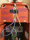
Here is my 2045 Decoder conversion. It may or may not be useful as your loco is much more recent vintage. I see your cab light wires are not color coded like the original 2045. You will need to do some wire tracing. You should take the roof off to see what you've got for the upper front and rear lights and cab lights. This is easy to do. Gently pry off the two roof running boards. Six screws will be exposed that secure the roof to the body. Other than that I think the following pics are self-explanatory. The front and rear lower right lights are connected to the decoder Aux1. The decoder is programmed to turn on Aux1 when the lights are on for both driving directions. This gives the "Swiss lighting mode" where the three driving direction lights and the lower right back light comes on if the lights are turned on. I've also programmed one decoder function button to turn on all the lights, Front, Rear and Aux1, for shunting mode lighting. On the original 2045 the cab lights came on with the directional lights. I separated the cab lights so they can be independently controlled on the decoder Aux 2 and Aux 3 outputs.

In the first picture below the left side decoder connections go to the motor block. The green and yellow to the motor +/- and brown and white to the left and right track pickups.

Ge 4-4 decoder install - 1.jpeg

Ge 4-4 decoder install - 1 (1).jpeg

Ge 4-4 decoder install - 1 (2).jpeg
 
Last edited:
Thanks Phil, that will be very useful.

I'll post my experience when the decoders have landed here... with International Post being disrupted just about everywhere by the pandemic, I'm expecting it might take a few months.
 
Has anyone actually done a bare bone up DCC installation on a LGB 23450? I've fitted other sorts of decoders to LGB locos in the past, but have always had the existing LGB analogue electronics available to work with (minimal as it may have been in some cases), so this will be a new experience for me.

I looked at the Ge 2/4 conversion info on the Massoth web site and it basically covers the LGB 22450 model which came with a LGB 10 pole interface. It also mentions "The LED illumination is supplied from [the] analogue PCB, so there is no change of decoder voltage needed."

Since there is nothing left from the original analogue electronics in my specific 23450, I am after some more advice. I'm assuming that I can plug the lighting cables directly into the Massoth 8230045 XLS, but that I may also need to do something about the setting the lighting voltage, which I gather can be done through the appropriate CVs. Is there likely to be anything else that needs to be done to compensate for the lack of the original LGB analogue electronics.

I've just received advice from GrootSpoor that my order for Massoth decoders has shipped, which has started my thinking about fitting one to this loco.
As a matter of practice when I convert an existing LGB locomotive to DCC sound, I remove all existing electronics. The Massoth XLS is self-contained so you don't need to, nor do I recommend, you wire it through the existing old factory circuit board, a potential point of failure of your installation down the pike which could possibly also blow the decoder. The Massoth Installation Manual and Configuration Manual are excellent in explaining the wiring requirements. Like Phil, for DIY DCC decoder installers, I also recommend to first wire the decoder's motor and track power terminals and the speaker. But I also recommend to first do a bench test in DC analog power, low voltage, to see if you get sound and movement. If so, then you've wired it correctly.......if you didn't wire it correctly the low voltage dc current is less likely to harm the decoder. You'll also need to dim the voltage on the lights terminals since the default setting is CV50=32, full track power. Most LGB locomotives use 5v. lights and 5v. smokers. I usually set CV50=4 to get about 6 volts which is the optimum output for LGB 5v. light bulbs.
 
The Massoth decorder order has arrived from GrootSpoor, so I will soon be able to start working on the Ge 2/4. Right now I am rebuilding a second hand ABe 4/4 so I need to get that done first!

E94E493F-9FB7-4785-A821-C0AA331EAB82.jpeg
 
Call me old school, I put current limiting resistors on all LEDs no matter what the source voltage (usually 5 volts or rectified track voltage).

I've seen far too many well meaning "helpers" reset a decoder and blow the LEDs.

Greg
Greg - Blowing the LEDs on a reset decoder is called "operator error." As you know, DIY installers need to know what they're doing and if not, it can be an expensive mistake.......blown decoder!
 
Back
Top Bottom