DCC in a HLW railbus

Huh? What?

Registered
Country flag
Wanna check thingsw.

In pic 1, you can see the wiring in the passenger compartment.Just right of center, there is a hole that goes down to the motor block. There are four wires coming out. Blue and grey should be the pickups. Heavier gauge red and black should be the motor. All the other lighter gauge red and black wires are for lights.

All the wiring exits to the left and goes into the luggage compartment.


Pic 1
37793658394_0637b7de39_c.jpg


Pic 2 shows where the wiring ends up in the luggage compartment. In here, all the reds and the blue are wired together and all the blacks and the grey are wired together.


Pic 2
38509158451_4b2e469817_c.jpg


The G8 decoder has hookups for Track +, Track -, Motor +, Motor -, Front light, and Reverse light. It also has 6 function connections, a ground and 3 x 12v+.

According to the Hartland documentation, Red and Grey are positive and Black and Blue are negative. This seems weird to me, as they have the grey (+) bundled with the blacks (-), and the Blue (-) is bundled with the Reds (+). Am I missing something here? Are they using the Blue and Grey leads as returns for the circuit?

So, following the documentation, Blue goes to Track -, Grey to Track +, Heavy Red to Motor +, Heavy Black to Motor -.

I don't think this thing has any reverse lights. so all red light wires would go to the Front light terminal? And then where do the blacks go? Ground?
 
Wanna check thingsw.

In pic 1, you can see the wiring in the passenger compartment.Just right of center, there is a hole that goes down to the motor block. There are four wires coming out. Blue and grey should be the pickups. Heavier gauge red and black should be the motor. All the other lighter gauge red and black wires are for lights.

All the wiring exits to the left and goes into the luggage compartment.


Pic 1
37793658394_0637b7de39_c.jpg


Pic 2 shows where the wiring ends up in the luggage compartment. In here, all the reds and the blue are wired together and all the blacks and the grey are wired together.


Pic 2
38509158451_4b2e469817_c.jpg


The G8 decoder has hookups for Track +, Track -, Motor +, Motor -, Front light, and Reverse light. It also has 6 function connections, a ground and 3 x 12v+.

According to the Hartland documentation, Red and Grey are positive and Black and Blue are negative. This seems weird to me, as they have the grey (+) bundled with the blacks (-), and the Blue (-) is bundled with the Reds (+). Am I missing something here? Are they using the Blue and Grey leads as returns for the circuit?

So, following the documentation, Blue goes to Track -, Grey to Track +, Heavy Red to Motor +, Heavy Black to Motor -.

I don't think this thing has any reverse lights. so all red light wires would go to the Front light terminal? And then where do the blacks go? Ground?
Best thing to do would be to chop the wires after labelling them all. Then you can use a Meter to see what does what. When you know that, wire the lot up to a set of Choc Blocks now with a Diagram of the Blocks to show what colour does what. Double check what does what then wire up to the decoder.

It is OK to rely on someone else's advice of what the wires do, but assemblers do not always get it correct during the Factory Build.

From my experience of pulling one of these apart the Colour Codes go Opposite between each Bogie which kind of makes sense even though both are not powered. Lighting wires will be joined up to give correct bulb lighting depending on direction of travel.
 
Use a meter to 'bell' out the wiring from the pickups (both bogies!) to your four wires from the 'blocks..

As has been said, it may well be that they are reverse-colours for each end of the vehicle.

You may also find that 'track +' and 'track -' refer to NMRA, and not large-scale, standards..

For the lighting:
In case you didn't know, DCC uses the 'decoder +' as a common, and the function outputs switch the -ve feed. - You need to be aware of this if the vehicle uses LED's for lighting.

As long as you use the left-side pickups for 'track +' and right-side for 'track -', the motor + and - should be 'as stated'.

HTH?
PhilP.
 
Alright. It lives.
Right now only the rear track pickups are hooked up.
Left to do...
Disconnect dcc board
Lengthen wiring
Hook up motor/rear track pickups/front track pickups
Figure out how to hook up lights
Mount board
Reassemble rail bus
Program as needed

 
Alright. It lives.
Right now only the rear track pickups are hooked up.
Left to do...
Disconnect dcc board
Lengthen wiring
Hook up motor/rear track pickups/front track pickups
Figure out how to hook up lights
Mount board
Reassemble rail bus
Program as needed

Smart looking railbus
 
Not used here Greg. Nearly all of our fasteners have a positive locking feature.
 
The jobbies shown by Greg are standard over here up to mains, also used for solid wire are these instead of connector blocks, again up to mains.

Art2122Big.jpg
 
Testing again. Both sets of pickups attached. This was the only 'oops' I ran into. when hooking up the wiring from the front truck, the red positive lead and the black negative lead have to be reversed. Red positive goes into the 'track -' terminal, and black negative goes into the 'Track +' terminal. otherwise you get a short circuit error.

The track was a quick throw down from spare track, which is really dirty, so it ran very well, in my opinion.


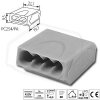
Chop the wires JonD? Tut tut, such violence! :rofl::rofl::rofl: The wire nuts used for connections let you gracefully disconnect the circuits.

By the way, do you call them "wire nuts" over there too?

wirenut-family.jpg


Greg
We used to use them in low current lighting circuits instead of a ceiling rose, still seen in old installations
 
Chop the wires JonD? Tut tut, such violence! :rofl::rofl::rofl: The wire nuts used for connections let you gracefully disconnect the circuits.

By the way, do you call them "wire nuts" over there too?

wirenut-family.jpg


Greg

Screw-its - glazed ceramic. I can remember them being used 50 years or so ago! With 230 volts you have to do better than those.
 
Testing again. Both sets of pickups attached. This was the only 'oops' I ran into. when hooking up the wiring from the front truck, the red positive lead and the black negative lead have to be reversed. Red positive goes into the 'track -' terminal, and black negative goes into the 'Track +' terminal. otherwise you get a short circuit error.
That is what I was trying to warn you about! Which is why it is always worthwhile to test out what wire goes where.
 
True, but I've spent most of my working life playing around Electricity Board gear, and some of the older stuff is so lethal that someone obviously didn't know!:whew:

I worked for English Electric once (well twice actually - met my wife to be there) - the test bed had a power house with slated boards, knife switches, rotary converters, and bare contacts. Probably the most interesting item (for me) was the salt bath reistor - having to fish out a dead rat! I knew that 1880's trams had this type so it was fascinating to see the blades being wound in.
 
I worked for English Electric once (well twice actually - met my wife to be there) - the test bed had a power house with slated boards, knife switches, rotary converters, and bare contacts. Probably the most interesting item (for me) was the salt bath reistor - having to fish out a dead rat! I knew that 1880's trams had this type so it was fascinating to see the blades being wound in.
Sounds like the motor cycle and combination rule, so damn dangerous it was safe because you had to be very careful or you fell off!:oops: The company where I did my apprenticeship used Mercury for a variable resistor in the test room right up until the 90's
 
Chop the wires JonD? Tut tut, such violence! :rofl::rofl::rofl: The wire nuts used for connections let you gracefully disconnect the circuits.

By the way, do you call them "wire nuts" over there too?

wirenut-family.jpg


Greg

They are called twist-on connectors over here. They are small and in different gauges
I use them for wiring up in certain situations (I am talking modelling here).
They are quick to set and also allow quick disconnection.

I have also used them when connecting up lighting strands inside the layout buildings. I squirt a little grease into them to stop any corrosion.
 
Back
Top Bottom