Could A 3 Pin Digital Decoder Be Made?

Sammler

Registered
I sent an email to Massoth a couple of days ago asking them if they could make a Digital Decoder for older 3 pin motor blocks, but wasn't sure if it would even be possible?

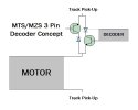
Would there be anyway of designing a new type of decoder that could control the speed and direction of the motor just by using the ground wire? I've read that DCC is almost like an AC voltage so perhaps there would be some way of controlling which side of the motor the voltage goes into?
 
The problem is you need to isolate the motor completely from the track power pickups, so that the decoder can control polarity of power to the motor independent of the track. A 3 pin block relies on one side of the motor being connected directly to the pickups, which is why you have to modify the block to isolate that common side of the motor and add the 4th wire.
 
Before LGB ever went to DCC they considered battery R/C as an adjunct. I sat down with their tooling engineer in the beer barrel car (the real one) one year at the Nuremberg Toy Fair where I patiently explained to him that LGB would need to modify all the motor blocks from 3 pin to 4 pin. His hands, and those of Wolfgang, went up in horror at the thought of the expense. So the battery R/C idea never went anywhere.
Needless to say, that LGB had to convert them anyway, to allow for MTS.
LGB had paid attention to their own German suppliers but could not face the ignominy of listening to a mere Colonial from the *rse end of the Earth. As Paul Keating so eloquently put it.
 
Converting an LGB three-pin block to 4-pin is really not at all difficult - all that is needed is to slip a short length of heatshrink tubing over the "white" pin so that the motor tab doesn't touch it, then gently bend the tab outward very slightly and (with the motor removed from the block, of course) solder a new yellow wire onto that motor tab. Sometimes you may need to make a VERY slight modification to the block itself by paring away just enough plastic to allow the new wire to sit right, but often even this is not necessary. Drill a very small hole in the motor cover plate to allow the new yellow wire to exit the block near the three existing pins, and you're done!

Older clamshell blocks are in some ways even easier - open up the block and snip away the brass tabs that touch the motor terminals, leaving the rest of the brass bus strip on each side in place. Solder new green and yellow wires to the two motor terminals (or you can use push-on connectors if there is room), lead these new wires up through the top of the block, then solder new brown and white wires to the little brass tabs that are visible on top of the block, where the original loco wiring picked up the lighting power. Bingo, you now have a DCC-ready block to be wired to the corresponding leads on your decoder!

Jon.
 
I concur with Z'd, having converted quite a few older 3 pins in my time for both DCC and Battery Operations.
JonD
 
I can see how modifying a 3 pin motor block is the only way to fit a conventional 4 pin decoder. What I was thinking was whether a manufacturer could make a new type of decoder that could be used with 3 pin motor blocks?

One idea was to allow the motor to be powered directly from the track and not the decoder, but to use a decoder wired in series with the motor to control whether the current coming from the nearside rail goes through the motor (to move the locomotive forward) or the current coming from the far side rail goes through (to make the locomotive move in reverse) as DCC alternates the voltage direction 800 times a second.

Perhaps a pair of diodes and transistors wired in parallel but with one of the diodes and transistors wired in the opposite direction. The chip could then control what direction of current to allow through to the motor by blocking the current moving in the opposite direction.

I`ve drawn a diagram to try and show what I mean (and if you hadn`t of guessed, I don`t know anything about electronics) :)


Attachments

  • 3 Pin Decoder Idea.jpg
    3 Pin Decoder Idea.jpg
    29.1 KB · Views: 36
I am pretty sure that would not work as the Motor needs to get its DC from the Decoder. You would be putting some AC into the circuit part and possibly even the circuited part of your concept. I am aware that LGB Motors can run via a DCC Direct Link. At worst I reckon this could Trash the Decoder, possibly the Motor as well.

Of course I stand to be corrected on this.
JonD
 
Afraid I'd agree with JonD, I really don't think this could work.... it's a key aspect of DCC that the track power must be totally isolated from the motor, as the track feed is a very fast cycle AC and the decoder must deliver pulsed DC to the motor.

Even if it WERE to somehow be electrically possible, I really couldn't see someone like Massoth making something like that just for backwards-compatibility of very old LGB locos - especially as converting them to run on DCC with a normal 4-pin decoder is a relatively simple job.....?

Jon.
 
Zerogee said:
...

Even if it WERE to somehow be electrically possible, I really couldn't see someone like Massoth making something like that just for backwards-compatibility of very old LGB locos - especially as converting them to run on DCC with a normal 4-pin decoder is a relatively simple job.....?
... I reckon if it were feasible and the market for them was large enough then Massoth would have made these years ago.

The diodes in the above circuit would simply block everything as they're opposing the flow through the transistors, but regardless of that; as has been written above the motor is driven by the decoder using PWM DC to vary the speed. It's easier for a programmable digital circuit to generate PWM pulses than it is to try and control the voltage in variable analogue fashion, and PWM usually gives better slow speed control. The PWM frequency isn't derived from the DCC signal frequency, and IMHO it wouldn't be practical or desirable to simply pass the DCC power directly to the motor as a kind of "half wave rectified pulses" as the above circuit suggests.
 
ntpntpntp said:
The diodes in the above circuit would simply block everything as they're opposing the flow through the transistors....The PWM frequency isn't derived from the DCC signal frequency, and IMHO it wouldn't be practical or desirable to simply pass the DCC power directly to the motor as a kind of "half wave rectified pulses" as the above circuit suggests.

It looks like I've drawn the diodes the wrong way around (told you I knew nothing about electronics!). I was thinking that PWM could control the amount of current going through the motor or perhaps the speed could be controlled by only allowing every 2nd, 3rd, 4th, 5th etc pulse to go through?

The "half wave rectified pulses" comment is what I was trying to say. I knew there was a proper electrical term for it. I think LGB use the same technique to control the direction of analogue signals and points.

Still, I thought I'd mention it. LGB were using 3 pin motor blocks for over 25 years so I thought that there must be a lot of 3 pin locomotives out there.

I believe that Marklin-LGB are also moving away from the Massoth digital decoders, so Massoth might need to find some new '3 pin motor' customers now that there biggest customer has moved on.
 
I fail to see why you are so in need of this even if it were possible. If you have the ability to make the circuit you suggest, what is the fear of taking a 3 pin Loco apart to make it compatible with an existing decoder.

As has been said before, you are trying to make an unholy mix of DCC, DC, AC and Analogue that will not work. I doubt that even if it were possible any Company would put in the cost to convert older Locomotives when a simple solution already exists.

JonD
 
The idea was to see if a manufacturer could make a 3 pin decoder that would allow collectors to convert their 3 pin motor locomotives to digital without making any permanent modifications to the locomotive. This would allow the locomotive to be restored back to it's original factory condition if the decoder was ever removed.
 
It's simple enough to restore a 3-pin loco after de-chipping it, should you ever need/want to do so... just connect the added yellow wire back to the "white" pin. You'd have to dismantle the loco anyway to remove the decoder.
To "de-chip" and restore an old clamshell loco, just connect the new green and yellow wires to the brown and white ones, respectively.

Jon.
 
As Z says, returning loco to DC could not be simpler. Also I would not worry too much about perfect return to 'Factory Condition' Second Hand prices being so poor these days, a bit if extra wire hidden inside the Chassis is diddly squat in the scheme if things. If it is Clean, Runs well and has all its bits. That is all you need to worry about.
JonD
 
Let's face it, if you've fitted a decoder and run it around your line it's no longer in factory condition anyway, it's just an old used model. I doubt anyone would go to the trouble of buying and fitting a decoder and not run it? If a collector's looking for "factory condition" they want a mint boxed model that's never been run.
 
Remember Hornby's Zero 1???

Well, this used 3 pin decoders, fitted pretty much like the diagram in reply #5

The along came an independant concern called ZTC systems....who made a digital system

What did ZTC stand for???

Zero TWO Controls!

Their system was desgned to be able to generate Hornby Zero1 signals and run locos fitted with Hornby decoders..

ZTC also sold their own decoders...I think it was ZTC208..a bit of googling is required here...
But this decoder...also a 3 pin device...could also operate on a DCC layout.
The ZTC command station could generate either Hornby Zero 1 signals...or DCC..giving an upgrade path

ZTC are still around...after quite a few changes in ownership.

On paper it seems possible to fit the ZTC Zero1/DCC 3 pin decoder to a 3 pin LGB motor block...and it should run on MTS, which is just about DCC...

But problems occur with current drawn, and the track voltage, either could kill the ZTC OO decoder

Malcolm
 
Zero 1 was a different method of command control, it wouldn't work with DCC, the data control protocols and method of transmission are entirely different. Zero 1 worked by sending data in between pulses of power, relying on a fixed frequency of AC track power and having the "module" (decoder) control the timing of switching that power to the motor. Hence the motor saw low the frequency 50Hz of the track power and tended to run very noisily.

With DCC the data signal kind of modulates the power, but it's not like a fixed AC frequency - there used to be a phrase used with DCC "the data IS the power". Presumably because the frequency of the signal on the track is not constant, the decoder generates stable PWM for the motor and hence has to have the motor completely isolated from the track.
 
NTP....I agree with everything you've written above.....

Zero 1 and DCC are worlds apart, and incompatible with each other....

Apart from this decoder that ZTC produced, which had a dual format.
I have done a quick google, and the ZTC 3 pin decoder may be their type 208..but the pdf didn't want to download

Fleischmann also made dual format decoders....FMZ or DCC, but they were only 4 pin???

ZTC probably spotted a gap in the market, the Hornby command centre was basic...as were their decoders..

But once a layout was fully Hornby Zero1, a ZTC command station could be used....and then slowly convert to the dual standard ztc XXX decoder..
Once all decoders were ZTC, the command station could then be switched from generating zero1 pulses, to dcc.

And then 'normal' dcc decoders could be used....ZTC had their own range of these too.

But the reviews at the time were not the best...and the support was a bit flakey

You've set me a challenge, to find out more on this ztc dual standard decoder!

Malcolm
 
Struggling to find any info on a ZTC 3-wire decoder so far. Yes you could get decoders like ZTC 203, 214 which understand zero-1 protocol, but they're 4 wires for pickup/motor as far as I can tell?

I have vague memories of seeing diagrams for decoder wiring in locos with some sort of 3 wire/chassis ground connection going on but I haven't found them yet. [edit] Come to think of it they were probably related to lighting using one of the pickups as common. [/edit] Everything I've ever read about DCC stresses isolating the motor - even ZTC's instructions.
 
Back
Top Bottom