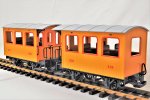
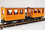
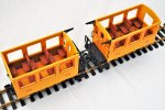
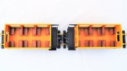
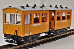
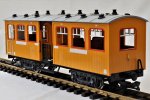
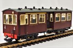
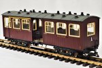
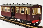
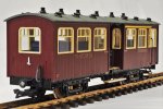
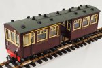
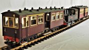
Claptowte Railway - Passenger Coach No 17 First/Third Auto-trailer

David1226

Registered
Country flag
Part 1 OF 3

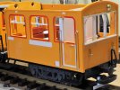
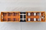
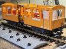
This is the twin of auto-trailer No 16, constructed in the same way, using two LGB Train 4-wheel coaches Toy mounted on LGB Jackson Sharp bogies. The only difference is that the forward compartment, incorporating the driver’s cab, is First class, with tables fitted.

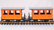
The starting point
dig 200223012.JPG

dig 200223013.JPG

dig 200223014.JPG

dig 200223015.JPG

dig 200223016.JPG

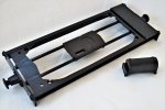
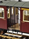
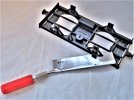
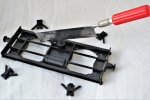
The first stage is to dismantle the two 4-wheel coaches. Having done that the new underframe is constructed using the frames of the two 4-wheelers. First the balcony ends are prepared for modification by removing the railings, brake stands, brake hoses and footsteps. The centres of the frames are then modified as below
dig 180227006.JPG

dig 180227007.JPG

dig 180227008.JPG

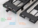
The ends are then prepared as shown below.
dig 191005003.JPG

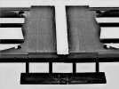
The buffer beams are drilled to accept bolts, each side, so that once the two ends are glued together, nuts and bolts can be added to add strength to the join. A strip of plasticard, of appropriate thickness, is then glued into the gap in the top decking. This is then scribed to match the planking/grain of the decking. The balcony steps are then screwed back on. An off-cut of plasticard is glued below the steps to span the gap. An off-cut of a spare step is then glued into the gap, fitting over the top of the plasticard to make one long step.
dig 191012012.JPG

A spare set of steps (left over from previous conversions) were fitted at the cab end, below where the driver’s door will be.

Plasticard mounts were created, together with tube pivot, to mount the bogies. The bogies were fitted with Al Kramer bright nickel plated solid turned brass wheels, imported from the US. These give a very low centre of gravity. The brake hoses are refitted to the buffer beams at each end of the new bogie underframe.

One last addition to the running gear was to add a plasticard guard iron to the cab end bogie. I had to do it this way as there would have been insufficient clearance if I had attempted to fit it to the buffer beam.

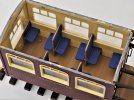
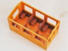
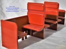
The next thing to tackle is the modifications to the two 4-wheel bodies that will form the front and rear compartments of the coach. First the seat units are removed to be modified. For the rear compartment the only modification to the seats is to reduce the height of the back rests in the centre pairs.
dig 220502001.JPG

dig 180227003.JPG


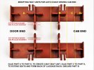
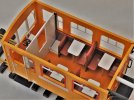
For the front compartment, the seat unit needs to be reduced in length to accommodate the driver’s cab. To fill in the gap between the front seats and the driver’s cab, a luggage rack is created on each side of the compartment, as shown below.
dig 220412001.JPG

dig 220612009.JPG


David
 
Part 2 of 3

The rear body was simply a case of framing the windows, using 2.00 x 1.5mm plastic strip. In order to Anglicise the appearance. Also, for appearance, I blanked off the slots, just below the roof line, into which the fixing tabs on the roof unit clips. A single Garden Rail Specialists GRS) etched brass lamp iron was attached to the rear of the body. Sign boards, from thin plasticard, were glued to the coach sides where the company name, coach number and Third class designation lettering would be applied.

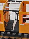
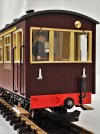
The real challenge was always going to be the driver’s cab. Fortunately, I had already built coach No16, this coach’s twin, so it was a simple case of copying that. The first thing I did was to cut out the aperture for the front windows. This was surprisingly easy to do, and, having squared off the sides with a file and removed any remaining moulded framing, I then framed this out using plastic strip.

Plasticard strip was added to the outside of the body, each side, to simulate the framing of the driver’s door. This was drilled and a short length of brass handrail wire was glued in to represent the door handle. On either side of the driver’s doors, holes were drilled and lengths of brass handrail wire were glued in for the (you’ve guessed it) handrails.

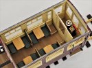
The partition between the driver’s cab and the passenger compartment is a piece of 2.00mm plasticard with a hole cut out for the window. The driver’s side was framed out with plastic strip to represent a door, with brass wire door handle. A strip of plastic channel was glued vertically down each interior side of the compartment and the partition just slots into these.

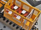
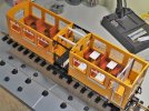
As this is a first class compartment, I have added tables between the seats. The tops were made from plasticard sheet, fitted with wooden cocktail stick legs. Plasticard off-cut strips were glued at an appropriate height below the windows, and the non-leg table end was glued on top of these.

The rest of the passenger compartment windows were framed out with the 2.00 x 1.5. plastic strip, to match the windows in the rear compartment. As with the rear compartment, the roof fixing slots were blanked off. Two GRS etched brass lamp irons were fixed to the front of the driver’s cab. I also added a brass coloured upholstery tack, above the front windows, to represent what I believe was a warning gong. To finish off the front of the coach I added a pair of windscreen wipers, the arms being brass wire, soldered to wiper blades made from scrap brass from the fret of the GRS etched lamp irons. Sign boards were added to the coach sides, using thin plasticard, where the company name, coach number and First class designation lettering would be applied.

dig 220531002 - Copy.JPG

dig 220531001 - Copy.JPG

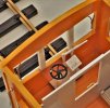
I created some rudimentary controls for the cab which are purely representational. I am not a rivet counter and I have no idea, and cannot be bothered to research, what the real controls would have looked like. I understand that they would have been minimal, little more that a regulator and a brake. I assume there would be a minimal number of gauges and switches. I fabricated a regulator lever and linkage from plastic strip. The brake stand was from the spares box, salvaged from another conversion. I believe that the driver could slow the train, using his brake, when coming into a station, but that the brakes could then only be released from the locomotive cab, before the train could continue.

dig 220612010.JPG

The other modification carried out to both bodies was the drilling of holes, at roof height, on each balcony end. These were then countersunk on the inside surface. This is to screw two lengths of plastic tube between the two bodies, to lock them together and increase rigidity, to prevent the coach from flexing in the middle.

This view also shows the new balcony railings. These were cut from a fret of railings left over from the construction of the Claptowte Railway Coach No 14, the 4-wheel Director’s Coach, and also used on Coach No 15, the Observation Coach. They were sourced from 12th scale dolls house accessories.

dig 220612007.JPG

The last element to be modified is the roof. This was created by taking the existing roofs and cutting approximately 4.0mm from each of the balcony ends, to get the overall length and fit correct. The two roofs were then glued together, end to end. The join was reinforced by curling a piece of plasticard of suitable length and width, and gluing this to the underside of the joined area. A suitably chamfered plastic strip, to match the existing moulded ribs, was glued across the top of the join, to conceal it.

Holes were then drilled, at appropriate locations, to accept GRS lamp tops and ventilators. The lamp tops were linked by conduit/pipework fabricated by brass wire and plastic rod.

The new combined roof can now be clipped on using the original tabs.

Views of the completed roofless coach

dig 220612006.JPG

dig 220531001.JPG

dig 220531002.JPG

The completed model prior to painting

dig 220612001.JPG

dig 220612002.JPG

The model was then disassembled into its various component parts, to be painted. Once painted, the model was reassembles and glazed and decals applied. I also added my own ‘Maker’s Plates’ to the underframe, which I had forgotten to add to coach No16, and which has now been so fitted.

dig 220712002.JPG

dig 220712004.JPG

David
 
Part 3 of 3

The last thing added was a driver figure. This was a standard LGB driver figure, salvaged from elsewhere and modified by removing the fire iron and the base on which the figure stood. I cut through the neck, to rotate the head, and the elbow, to move the arm before gluing them back on. The figure was then be repainted.

The finished model

dig 220712006.JPG

dig 220712007.JPG

dig 220712009.JPG

dig 220712008.JPG

dig 220712013.JPG

dig 220712011.JPG

dig 220712015.JPG


David
 
Another superb build David :)
 
Excellent and very clean build!
It is not motorised?
Henri

No, an auto-trailer is not itself powered. It is coupled to an appropriately 'auto fitted' steam locomotive and run as a push pull unit, negating the need for the loco to run around the coach at the terminus. When pulled, the train is controlled, as normal, from the locomotive cab. When pushed, the train is controlled from the driving cab at the front of the coach. The necessary controls are worked via mechanical linkages running under the coach and connected to the linkages on the loco. The idea was used extensively by the Great Western Railway in the UK, for lightly used branch lines. Where more capacity is required, an auto-trailer could be fitted to each end of the locomotive, the forerunner of the Diesel Multiple Unit

Now that I have built two auto trailers, No16, an all Third Class, and now No17, a First/Third Class, I shall run them as an auto-train with a steam locomotive in the middle. As soon as I can, I shall set up some photos of the assembled train.

David
 
Aha! In Dutch such thing is called a 'stuurstand' carriage (google says 'helm position'). I don't know if these were used with steam engines, but definitely with diesel/electric powered locomotives. In fact I'm building such a thing myself as the RTM used to have two of these. Well, the project was started two years ago and has been abandoned ever since...

Edit: found it! RTM M65 and ABP422 tram
 
Last edited:
Ah! A 'UFO' Henri..
We all have them.

An Un-Finished Object.
;) :rolleyes::nod:

PhilP
 
Another top build and interesting thread, nice one David
 
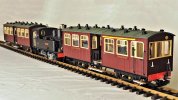
A couple of views of the complete auto train, with Coach No17 leading, Coach No 16 bringing up the rear, and locomotive No 3 Yvonne, in the centre providing the motive power.

dig 220713001.JPG

dig 220713005.JPG

David
 
Very nice. As a matter of interest an Auto Trailer would likely have as many as 3 pipes to control things, looking at GWR varieties there is a Vac Pipe possibly an Air pipe and another for unknown purposes. Also likely some additional pipe and tanks on the loco though pumps generally hidden on GWR locomotives. Yes I know you are building a freelance line and could argue your line has different methods. But at least another pipe all round would add fidelity.
 
Very nice. As a matter of interest an Auto Trailer would likely have as many as 3 pipes to control things, looking at GWR varieties there is a Vac Pipe possibly an Air pipe and another for unknown purposes. Also likely some additional pipe and tanks on the loco though pumps generally hidden on GWR locomotives. Yes I know you are building a freelance line and could argue your line has different methods. But at least another pipe all round would add fidelity.
On GWR stock, the extra pipework you speak of, as well as the mechanical linkages, are all below buffer beam height, in the space, on my model, taken up by the LGB coupling, and the need to give that room to swivel from side to side. As stated in the text on the construction, it was not even possible to add guard irons under the buffer beam because of this. As I am not a rivet counter and the model does not represent any prototype, I claim artistic licence.

David
 
Another beautifully precise piece of work, which you have explained in detail; the BR-style toplights Anglicise the design very effectively.
 
Very nice. As a matter of interest an Auto Trailer would likely have as many as 3 pipes to control things, looking at GWR varieties there is a Vac Pipe possibly an Air pipe and another for unknown purposes. Also likely some additional pipe and tanks on the loco though pumps generally hidden on GWR locomotives. Yes I know you are building a freelance line and could argue your line has different methods. But at least another pipe all round would add fidelity.
High fidelity if on the roof I imagine...
 
Looks great David, I really like the detail of the linkage in the control cabin, it looks very believable to my eyes. It's amazing what little details like the additional window frames make to those basic toy train coaches.

Very nice. As a matter of interest an Auto Trailer would likely have as many as 3 pipes to control things, looking at GWR varieties there is a Vac Pipe possibly an Air pipe and another for unknown purposes. Also likely some additional pipe and tanks on the loco though pumps generally hidden on GWR locomotives. Yes I know you are building a freelance line and could argue your line has different methods. But at least another pipe all round would add fidelity.

As David mentioned the GWR had mechanical linkages, which is what limited them to 2 coaches either side of the loco. The rest of the big three (and their constituent companies) used a variety of vacuum or air powered systems. On the LMS' vacuum powered stock this required a second vacuum pipe, usually yellow for the regulator control, to differentiate it from the usual red pipe for brakes. I've just finished an OO scale model of such a train and got lots of useful info from this site, for anyone who might be interesting in doing something similar.
 
Looks great David, I really like the detail of the linkage in the control cabin, it looks very believable to my eyes. It's amazing what little details like the additional window frames make to those basic toy train coaches.


As David mentioned the GWR had mechanical linkages, which is what limited them to 2 coaches either side of the loco. The rest of the big three (and their constituent companies) used a variety of vacuum or air powered systems. On the LMS' vacuum powered stock this required a second vacuum pipe, usually yellow for the regulator control, to differentiate it from the usual red pipe for brakes. I've just finished an OO scale model of such a train and got lots of useful info from this site, for anyone who might be interesting in doing something similar.
That of course is true, but there were still more than 1 pipe on all the GWR Auto Trailers that I have seen pictures of. At least 1 would be for the Vac Brake and another for Steam Heat.
 
Just to let you know what the connections are on a GWR Auto loco:-
Vacuum pipe., steam heat pipe both as a 'normal' loco.
Additional items for Auto working,
Rod for regulator under buffer beam, whistle cable at top of coach level, jumper cables for bell communication system - this is two cables about half inch diameter on a common connector.

As driver in the Auto coach you can open and close the regulator, apply the brake and sound the whistle. The Auto Fireman (special grade between fireman and driver) has to release the brakes, adjust the cut off, fine tune the regulator setting as well as his normal firing duties. The bell system allows the driver to give an indication of what he wants to the fireman with a simple code system.

I can tell you that Auto Fireman is the best job on the railway as you have total control over everything! As Auto Driver in the vestibule you just hope your mate is on the ball !
 
Excellent work as per usual David....
 
Back
Top Bottom