Buffer capacitor to single motor analogue LGB locomotives

Hi,
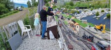
I run a garden railway in Norway. All my locomotives are analogue, no decoders. Locomotives with double tractionmotors have no problem with negotiating poor contact from the tracks. Single motor locomotives however do have this problem. Where contact with he tracks is poor, or on points, some of them don't run smoothly. I thought adding a 2200 uF cap would do the trick, but no.
Apart from keeping the tracks clean, is there any way I can give my locomotives this extra push when they need it?
I run my installation from two 12 V 87 Ah batteries in series (24V) through some electronics to simulate brake and inertia effect.
I have some old school books with some DIY circuitry to supply the tracks/ loco's with PWM, but I'm afraid this will kill the motors (heating up)
Any suggestions from you other analogue folks?
 

Attachments

  • received_860650861576469.jpeg
    received_860650861576469.jpeg
    314.2 KB · Views: 0
The problem with a 'stay alive' capacitor for DC locos is that when the capacitor gives its 'kick', it is uncontrolled in terms of voltage. When using such a device with DCC, the voltage is controlled by the chip, and thus gives steady running when the capacitor is asked to do its work.

I pondered this question for a long time, as I also run DC and my locos are all skate free - relying entirely on wheels only for contact.

I arrived at the following position.

Large steam locos (typically 2-8-0) which have tender pickups as well remain track powered.

Small locos such as 4w or 6w diesels or 0-4-0 steam have been converted to batter power.

I had two steam outline locos, with tender pickups - a 4-6-0 which only collected from the drive wheels and a 4-4-0, which I converted to flywheel motors.

Have you checked your points / turnouts to make sure that there are no dead rails? I ask that, because while my locos performed quite acceptably over my turnouts, a visiting LGB Sumpter Mallet stalled on one turnout, and it was only then that I realised that I had a failed jumper wire in the (long) turnout.
 
Most controllers are PWM these days, and DCC certainly is.
This should not be a problem for the motors in your LGB locomotives.

I think your problems are a combination of short wheelbase locomotives, and LGB plastic frogs.

You need to check all wheels and skates, along each side of the locomotive are working as they should. Clean the backs of the wheels, where the carbon brushes rub. Check these are free to move, and not worn. Clean the tyres on the locomotives.

If you can arrange pickup from a trailing vehicle (a tender perhaps?) you can feed this forwards to the locomotive.

Trying to add a power buffer to an analogue locomotive is not so easy.

PhilP.
 
The problem with a 'stay alive' capacitor for DC locos is that when the capacitor gives its 'kick', it is uncontrolled in terms of voltage. When using such a device with DCC, the voltage is controlled by the chip, and thus gives steady running when the capacitor is asked to do its work.

I pondered this question for a long time, as I also run DC and my locos are all skate free - relying entirely on wheels only for contact.

I arrived at the following position.

Large steam locos (typically 2-8-0) which have tender pickups as well remain track powered.

Small locos such as 4w or 6w diesels or 0-4-0 steam have been converted to batter power.

I had two steam outline locos, with tender pickups - a 4-6-0 which only collected from the drive wheels and a 4-4-0, which I converted to flywheel motors.

Have you checked your points / turnouts to make sure that there are no dead rails? I ask that, because while my locos performed quite acceptably over my turnouts, a visiting LGB Sumpter Mallet stalled on one turnout, and it was only then that I realised that I had a failed jumper wire in the (long) turnout.
Thanks for your reply. I checked the turn outs /points for dead rails allright, they are in good order (after repair of some jumper wires a long time ago) . There is no problem with loco's with tenders with pickups, they run smoothly. The small loco's will be used on industrial layouts, just running back and forth. Battery power could be a solution for these. Why did you remove the skates?
 
Most controllers are PWM these days, and DCC certainly is.
This should not be a problem for the motors in your LGB locomotives.

I think your problems are a combination of short wheelbase locomotives, and LGB plastic frogs.

You need to check all wheels and skates, along each side of the locomotive are working as they should. Clean the backs of the wheels, where the carbon brushes rub. Check these are free to move, and not worn. Clean the tyres on the locomotives.

If you can arrange pickup from a trailing vehicle (a tender perhaps?) you can feed this forwards to the locomotive.

Trying to add a power buffer to an analogue locomotive is not so easy.

PhilP.
Thanks for your reply. It is the short wheelbase loco's that are the problem, yes. Like you suggested, I cleaned and checked all the things you mentioned, it is part of the regular maintenance on the rolling stock. I have some further questions about PWM, can I bother you with technical questions about this?
 
Thanks for your reply. I checked the turn outs /points for dead rails allright, they are in good order (after repair of some jumper wires a long time ago) . There is no problem with loco's with tenders with pickups, they run smoothly. The small loco's will be used on industrial layouts, just running back and forth. Battery power could be a solution for these. Why did you remove the skates?
I don't have LGB locos - none of my locos ever had skates.
 
Simple analogy for PWM (Pulse Width Modulation)
Imagine you have a light bulb and a switch:
If the switch is ON all the time, the light is fully bright.
If the switch is OFF all the time, the light is off.
But if you quickly flick the switch ON and OFF, faster than the eye can see, the light will appear dimmer — like it's halfway on.
This fast flicking is what PWM does — only it does it electronically and very fast.

The width of the “on” time is being changed — that’s the “pulse width”.
If it's on 90% of the time, it looks almost full power.
If it’s on 50% of the time, it looks half power.
If it’s on 10% of the time, it looks very dim or slow.
This is called the duty cycle — how much of the time the signal is ON.

Think of it like this (O = ON, . = OFF):
90% ON: OOOOOOOOO.
50% ON: OOOOO.....
10% ON: O.........
 
Welcome to the forum Marcel. No questions will go unanswered on here, thats one of the reasons for the forums' existence. 12V seems low, usually its 24Vs, but obviously you have success with 12. I assume you have jumper wires or several feeds around your layout, it does look rather large.
 
Welcome to the forum Marcel. No questions will go unanswered on here, thats one of the reasons for the forums' existence. 12V seems low, usually its 24Vs, but obviously you have success with 12. I assume you have jumper wires or several feeds around your layout, it does look rather large.
That is good to know, thanks. No, it is a 24 V DC layout, two batteries in series. regulated down to 16 volts DC and some electronics (analogue) to simulate braking and inertia. I have several feeds, yes. Length of the layout is 18 meters, dogbone-ish, so about 40 meter with continuous track.
 
Back
Top Bottom