Bachmann Baldwin "industrial" mogul conversion

maxi-model

UK/US/ROW steam narrow gauge railways 1:1
Country flag
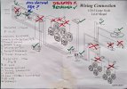
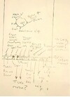
Well, I started this on the "workbench" thread. Got down to a start today. Looks simple enough, however, the sketchy schematic supplied by Bachmann seems to be possibly a different layout in the PCB wiring dept. So, I thought this might be a useful opportunity to familiarise myself with what is on this PCB and what wires go where, what they do and what will be redundant. First thing trace the wires and their functions. Drew a "map" so I can vizualize what is going on and work out how to wire up and package the battery/rc/sound convertion. Note, ?'s have been answered. Most of that PCB seems to be about the generating of a chuff. So, next to order the bits - Micron Rx65c with F&R directional lights, 3 functions wired on sounds. A micro MLS sound card. Choice - 2 x 8 AAA NiMH or 2 x 5 AA ? Having tested on dc I think it is going to need the volts for the smoke generator (might switch too a Seuthe) and lights. PhillP - Incoming ! Next, see what I can rationalise in the boiler barrel and how to add weight. Coupler will be sorted, Ihave a few Kadee bits lying around. Get it to NMRA Fn3 height and looking a bit more "prototypical". I've fitted an Ozark link and pin at the rear. Max

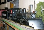
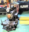
The loco, nice and clean with little wear and a good quiet motion and gears. Lights working, did not test the smoke generator. Will do that when I open up the boiler barrel. Decide then if I spend money on Seuthe unit over stock supplied.
20260301_123338.jpg
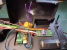
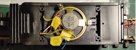
Inside the tender, as Bachmann intended
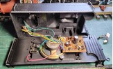
20260301_110655.jpg
"Mental map" of board to work out what goes where. The Bachhmann supplied schematic does not match up and has no colour coding. Who drew them ? :devil:20260303_173136.jpg
For those still looking, here is the real thing, wires removed.
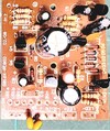
20260303_172624.jpg
For you printed circuit freaks, the reverse of this PCB
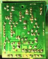
20260303_172243.jpg
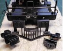
And finally, the gutted tender with some redundant bits razor sawed off. Maximisem space. Noticed the coal load can be popped out. Giving me ideas.20260303_173548.jpg
 
Last edited:
Yep, you can take it all out, but, as you have wisely done, you need to know which wires from the loco are sound and which are lights.

You should also have tender pick-up wires ................... but then, you're not really interested in those :rolleyes::rolleyes: and to think that I bought a pair from the good ole' USofA to give me extra pick-ups on the whale back tender :rock::rock:

For anyone interested, there is a cheap way of boosting the standard Bachmann sound card so that it produces a better chuff ........ if I can find where i stored that info on my PC :oops:
 
Yep, you can take it all out, but, as you have wisely done, you need to know which wires from the loco are sound and which are lights.

You should also have tender pick-up wires ................... but then, you're not really interested in those :rolleyes::rolleyes: and to think that I bought a pair from the good ole' USofA to give me extra pick-ups on the whale back tender :rock::rock:

For anyone interested, there is a cheap way of boosting the standard Bachmann sound card so that it produces a better chuff ........ if I can find where i stored that info on my PC :oops:
Ooh, that might be interesting Rihno. I've always been a bit intimidated by these old Bachmanns with their confusing schematics and serpents nest wiring. Really they are quite straight forward when you sit down and stop panicking. Still wouldn'twant to put a ESU Loksound in one :oops:

I have my vey first Fn3 loco, bought from St Aubins 20 years ago, Connie close out special. It's the last in line for conversion, I keep on overlooking it for some reason. It has the new grass bear fitted and identity. I have a very old Tony Walsham (RIP) RCS rc system, RX & TX aand Ni Cad pack. Came with my Goose 7 a couple of years ago (yes it all still works) but it is without the sound module. Now if the Bachmann sound PCB could be improved then it might sway me to reuse. The Connie still has its chuff sensor fitted. A full retro conversion. Ok, no bell or whistle but I could live with that, a sort of freebie conversion. Appeals. Max.

The old Connie
Connie 001.JPG
 
OK, found it Google George Schreyer Bachmann sound modifications - apparently this guy was a rocket scientist :eek: I've done a couple of sound boards like this - the sound still isn't mega-loud, but for a few coppers, the chuff becomes nice and crisp.

If I want good, reasonably loud sound, I use MLS :nod::nod:

A New Version of the Bachmann Sound Board​

As of sometime in 2000, Bachmann has changed the sound board. The new circuit can be identified from the outside of the tender as it has a volume control knob underneath the tender floor. It no longer will blow a continuous chuff when stopped, but the chuff profile is poor, it's decay is way too long. This can be fixed.

I've traced out the circuit of the new board as shown below. It is basically the same circuit, but some new parts are added to cause the unit to blow a constant length chuff each time it is triggered instead of chuffs that vary in length as compared to locomotive speed. Actually, once you've added the circuit described above to stop the continuous chuff, the old version works better. Real engine valves move faster at higher engine speeds and the chuff bark will shorten with increasing speed. The old system would do that, the new one won't. It is not practical to adapt the uneven beat chuff method to the new circuit but you can add new trigger wires to the sound drum to get four beats per driver turn.

Note that there are some differences, especially in the noise generator section, of this schematic as compared to the ones above. This is most likely an error on my part. Since I've checked this schematic carefully, it is probably correct and the ones above are probably wrong, but it really doesn't matter as none of the modifications involve that part of the circuit.

new bachmann sound circuit schematic

Q1 is a new part and key to the change in the circuit. When the chuff switch closes, a packet of charge is delivered through C1 to the base of Q1 which turns Q1 on until C1 charges up. This time constant determines the chuff duration as Q1 now acts like the chuff switch on the old circuit and activates the noise generator and amplifier. It also charges C10 in the process. When Q1 turns off, the noise generator and amplifier continue to run on the charge stored in C10. The problem is that C10 is much too large and the circuit just dies off much too slowly dragging out the decay of the chuff. The fix is the reduce the value of C10 by about a factor of 5.

new bmann sound board
C10 is the largest part on the board and it is labeled on the board so that it easy to find. Just remove the old C10 and install a new capacitor rated between 330 and 500 uF at 10 volts or better in its place. The part I used was a little too tall to fit right back where the old one was, so I hung it off to the side of the board. Pay attention to the polarity marking on the board and the part, they MUST match.

I also installed another capacitor in parallel with C8, the output coupling capacitor, to give the sound a little boost in the low end. The difference is minor, but it is detectable. The chuff has a little more authority than before. Increasing the values of the other coupling capacitors doesn't seem to help this board as much as the older one.

The new board seems to have some leakage that will flatten the battery over a period of a few months. If you are not going to use it for awhile, it might be best to turn it off with the volume control under the tender.
 
So, next job after gutting the tender and tracing its wiring has been to sort the front coupler. I had a few odd Kadee bits lying around to cobble something up. When you convert a few old Bachmann couplers to Fn3 height standard, to match the Accucraft and more recent Bachmann offerings, this tends to happen. Could not belive my luck. Bit of hacking around at the front and fettling and the finished article ends up at the exact Fn3 height. And it's secure enough to be functional to pull the heaviest loads this little loco can handle, with some extra lead in its belly. Looks quite neat, even if I say so myself. Next a fall plate at the back of the cab and some "greedy bars" around the coal bunker. Max

Original unmolested Kadee "cobbled up" on left, chopped and cropped on right. More surgery on on the pilot and its support to get it to fit in.
20260307_130133.jpg
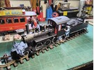
Finished article. Big tender in background belongs to Connie that is getting the "vintage" RCS RC treatment at the same time.
20260307_140448.jpg
 
Gosh, it's been a while since I posted about any work on this project. I need to focus a bit more. So a little picture update.

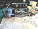
I have a plan.............of sorts. It gets annotated as I go along. I find it very reassuring :D
20260912_170251.jpg
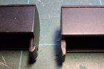
First picture below. Tender interior needed carefull prep. grinding the deck and tender top flat to remove lots of of little bits that intruded on a very maginal battery installation. You can see the "witness marks" where I went to work.There is a total of 16.8v avaliable from an 8 cell + 6 cell pack, AA cell size NiMH. Next, the tolerances on battery pack height to fit were about 0.3 mm, so battery packs were glued together only rather than shrink wrapped as well. Last, the tender tool boxes needed to be easily released as they would cover switch and charge socket placements, so a tab on one end of each was filed flat.
20260519_192729.jpg20260519_211240.jpg20260519_192804.jpg
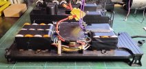
So, first image below, here is the tender now with battery pack fitted. I have made some "rafts" that an Rx65c Esc/Rx and mini MLS US steam sound card will sit on. They were selected for their compact design and functionalities. They, with their wiring, will fit under the coal load, when done. The coal load has had its tabs, similarly to the tool boxes, modified, they still sit tight but are easier to remove for access. Below that a quick try out to check everything else will fit. The tender top fit snugly onto its chassis without any forcing and the "rafts" offer a similar fit. Just 2 JST's are needed so the tender top, with its switchgear & socket harness, lifts free.
20260913_175332.jpg20260909_141201.jpg
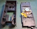
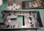
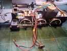
Before I can connect up the bits that do the magic in the tender I need to take a look inside thd loco's boiler as I decided to delete the redundant stock PCB and rework the wiring. First image is what greets you once all the bits are released from the boiler's upper half. And below that what is left over after the redundant bits are removed and some wiring "reassigned". What was a track power input from the tender truck pickups to old board is now the motor's input from the Esc. The front LED still feeds back to make a circuit with the one at the back but its resistor is moved to the tender as is the rear LED's. The smoke unit is wired parallel to the motor's voltage input and that circuit is switched, note the brass tabs that locate to the smoke units trough. There was a voltage regulator on thd PCB that looked as though it was on the smoker's circuit. Yes, I have tested the smoke generator at different voltages. The chuff trigger remains as supplied. Before I get the loco back together I'll optimise the space available in the upper boiler space to add some lead. With all that extra weight in the render the loco will need a little extra adhesion. As a side note, Bachmann'x wiring colour coding seems to have no rational. The front LED wires change colour (both) 3 times on their journey to the tender. It's noted on my plan below, just like the assignations on the ditched sound card. So that just leaves.........
20260912_162147~2.jpg20260913_170533.jpg
 
Well, I started this on the "workbench" thread. Got down to a start today. Looks simple enough, however, the sketchy schematic supplied by Bachmann seems to be possibly a different layout in the PCB wiring dept. So, I thought this might be a useful opportunity to familiarise myself with what is on this PCB and what wires go where, what they do and what will be redundant. First thing trace the wires and their functions. Drew a "map" so I can vizualize what is going on and work out how to wire up and package the battery/rc/sound convertion. Note, ?'s have been answered. Most of that PCB seems to be about the generating of a chuff. So, next to order the bits - Micron Rx65c with F&R directional lights, 3 functions wired on sounds. A micro MLS sound card. Choice - 2 x 8 AAA NiMH or 2 x 5 AA ? Having tested on dc I think it is going to need the volts for the smoke generator (might switch too a Seuthe) and lights. PhillP - Incoming ! Next, see what I can rationalise in the boiler barrel and how to add weight. Coupler will be sorted, Ihave a few Kadee bits lying around. Get it to NMRA Fn3 height and looking a bit more "prototypical". I've fitted an Ozark link and pin at the rear. Max

The loco, nice and clean with little wear and a good quiet motion and gears. Lights working, did not test the smoke generator. Will do that when I open up the boiler barrel. Decide then if I spend money on Seuthe unit over stock supplied.
View attachment 353812
Inside the tender, as Bachmann intended
View attachment 353813
"Mental map" of board to work out what goes where. The Bachhmann supplied schematic does not match up and has no colour coding. Who drew them ? :devil:View attachment 353814
For those still looking, here is the real thing, wires removed.
View attachment 353818
For you printed circuit freaks, the reverse of this PCB
View attachment 353819
And finally, the gutted tender with some redundant bits razor sawed off. Maximisem space. Noticed the coal load can be popped out. Giving me ideas.View attachment 353817
I'm pretty certain that board is essentially all chuff. There is a cheap way of getting a better 'chuff', but it's nowhere near as good as an MLS sound card
 
I'm pretty certain that board is essentially all chuff. There is a cheap way of getting a better 'chuff', but it's nowhere near as good as an MLS sound card
The PCB in the boiler is solely the loco's main power distribution and "management" board. The board in the tender, that I also deleted, is the chuff sound board. It has some pads, that have the sole purpose of linking power management, like F&R LED circuits and pick up inputs, they are Isolated from the sound board's circuitry. Those pads wire direct to the boiler mounted PCB.

Your chuff board enhancement reccomendation link, and its text, is in post #4. If anybody wants a Bachmann chuff board to play with they are welcome to the one I removed here, gratis, with its volume control. It's only source of power is 9V battery pack, nothing from the track or loco's power distribution PCB, it is not connected. It receives a chuff "signal" from two metal strips acting on a rotating segmented axle, providing open/closed circuit triggers fed back to this board.
 
Back
Top Bottom