James Stuart
Registered
Hello,
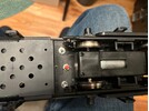
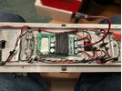
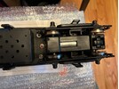
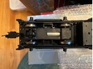
I recently purchased an Aristo Craft FA-1 loco and would like to know what the RED button at the bottom of the loco is for. Also, I'm assuming, to run off the batteries, the 3 way switch needs to be thrown toward the middle of the loco, not toward the outside and to run off track power, the opposite applies. In the first attached photo, the port above the RED button is for the charger plug to be inserted, right? I have a vintage Aristo Craft charger on order. The board in the second photo shows a mother board of sorts. Is that also a receiver for battery control and which kind of controller would I need to run in battery mode? Lots of questions, but thanks very much!
Jim Rohrbach
San Mateo, CA, USA