Another 12070 query

Ralphmp

Registered
6 Jan 2010
1,640
228
72
Herts
Country
England
Best answers
0
Country flag
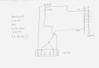
I know this topic has come up on several occasions before, but I couldn`t find a schematic showing how to wire up the 12070 supplementary switch to operate signals in conjunction with point movement. So could some kind soul confirm that what I`m proposing to do (shown below) is correct? (Note - I run Massoth so track voltage is 23V, the "Green" and "Red" in the diagram are LEDs with appropriate resistors already attached)


Also, in view of comments about the microswitches failing, I circuit tested mine with a multi-meter and found that the two connections nearest the middle (numbers 3 and 4) don`t appear to do anything. There is no continuity between them or either of the input connections (numbers 2 and 5). Number 1 works with Number 2, and Number 5 works with Number 6 but that`s it. As this is the same on 3 new switches I assume it`s designed this way. Could someone perhaps explain what the point of these "dead" connections is?

Many thanks
Phil


Attachments

  • 12070 connection diagram 800x640.jpg
    12070 connection diagram 800x640.jpg
    78.6 KB · Views: 24

muns

Well-Known Member
Staff member
GSC Moderator
24 Oct 2009
5,718
130
Southampton, U.K.
www.gardenrailoutlet.co.uk
Best answers
0
Country flag
Hi Phil,

The 12070 contains 2 micro switches, one is connected to terminals 1, 2 & 3 with 2 being common. 1 & 3 are switched based on the position of the point motor. Likewise with 4, 5 & 6 with 5 being common.

If the 12070 is good then you should not need to connect 2 & 5, just 2 and the cable from 6 would be to 3.
 

Ralphmp

Registered
6 Jan 2010
1,640
228
72
Herts
Country
England
Best answers
0
Country flag
Mark

Thanks for the reply. This makes life a bit easier for me!

As the 2 switches are independent, presumably I could use one 12070 to operate 2 signals - terminals 1,2 and 3 for one, and 4, 5 and 6 for the other?

Best wishes
Phil
 

stockers

Trains, aircraft, models, walking, beer, travel
24 Oct 2009
25,631
3,795
66
Nr. Ashford, Kent. England.
Best answers
0
Country flag
Yes you could, but equally, you could run the lot off of 1,2 and 3. The switching load for signals should not be too high for the capacity of the switch.
 

PhilP

G Scale, 7/8th's, Electronics
5 Jun 2013
33,709
3,551
Nottingham
Best answers
0
Country flag
Yes Phil,
Move your wire from 6 to 3 for the first signal, leaving your +ve. supply to 2 and 5..
Then wire your second set of signal LED's to 4 and 6.

Phil (PhilP, one of the other ones!)

OR,
As Stockers says run the lot off one switch..
Then if the first switch fails, just move the wiring to the other one.
 

Ralphmp

Registered
6 Jan 2010
1,640
228
72
Herts
Country
England
Best answers
0
Country flag
Thanks guys.

This simplifies what I was trying to do considerably. Not sure why there isn't a basic diagram with the switch when it's shipped from the factory. There's a scrap of paper warning about mis-aligning the switch when you install it with the EPL, so if they made this a bit bigger they could add a simple wiring schematic. Surely can't add to the costs significantly.

Anyway, all's working as I wanted so once again the forum comes to the rescue!

Best wishes
Phil
 

Ralphmp

Registered
6 Jan 2010
1,640
228
72
Herts
Country
England
Best answers
0
Country flag
I guess Marklin / KGB must have heard me - opened up a 12070 I bought just last week to find that the packaging with this one includes a couple of pictures to illustrate how you could use the switch!!