Distrackted
Registered
This locomotive is equipped with a Direct Decoder Interface. My intention was to install an LGB 55021 motor decoder and a Massoth S sound decoder - a simple project. However, I have a penchant for being able to write and read CVs flawlessly without having to open up the locomotive again, and I wanted to be able to turn the cab light on and off independently.
I find that if both decoders are connected to the programming track at the same time, CVs can't be read reliably, and it is best if you can disconnect one while reading the other. I knew that I would require one switch to disconnect the sound decoder. I had originally thought that the multi-function switch in the cab would disconnect the 55021 from power, but it turns out this switch has no purpose once the decoder is installed - so two toggle switches were required. I couldn't just leave the 55021 plugged onto the direct interface board since there was no way to isolate the power to it. I flipped the 55021 decoder the right way up and made jumper cables to connect all the appropriate pins to the interface, except the track power inputs which I could connect to a switch. That turned out to not isolate the decoder either, and in the end I removed all except the motor + and - jumpers to the interface. To allow the cab light to be operated with function A1 of the 55021 I did had to snip the cab light wires at their connection plug on the interface board and connect them directly to the decoder function outputs.
In retrospect it would have been simpler to remove the decoder interface entirely, but I really like the way the motor block plugs directly into the interface from underneath on this locomotive.
I'm sure others would have found much better ways of doing this, but I'll document what I did in case some of the ideas are of any use. In particular: (1) a custom, low profile speaker housing, which tucks nicely into the cab ceiling; (2) location of two toggle switches mounted on the "hump" in the cab with a custom 3d printed saddle; (3) a good way to connect a jumper wire to the sockets on the decoder interface (I tried making pins to go inside the sockets, but they were wobbly - an external "collar" is much better!, and; (4) 3D printed riser block to mount the 55021 above the interface board and Massoth S decoder.
Here are instructions to open the locomotive:
To remove the motor block:
- remove the very back screw and the second from front screw of the motor block underneath - the motor block will drop down and unplug from the interface board.
To remove the hood:
- undo the four screws (two on either side of the motor block housing underneath) - easier done with the motor block removed.
- with the locomotive the right way up, very gently pry the long rails along each side of the hood up to release the lugs which are press fit into square holes.
- turn the railings outwards towards 90 degrees from the hood to unhook them from the cab. The railing has a short 90 degree bend on the end to retain it to the cab (hint: if you look inside the cab you can see the railing ends to check their orientation).
- carefully pry the two front hand rails outwards at the top to remove the top ends from the holes next to the radiator (use a plastic tool to help pry them out if they don't come out easily).
- keep the hand rails gently pried apart to prevent the ends from scratching the hood.
- lift the back end of the hood up a bit and slide it slightly forward, then lift it clear of the chassis.
- the wires from the front headlight can be unplugged from the interface board so that the hood can be set aside.
To remove the cab roof:
- carefully remove the 4 tiny screws (2 at the front and 2 at the back). They are easy to lose!
- the cab roof should lift off
PICTURES BELOW:
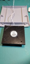
Here is the 3D printed speaker housing that fits around the magnet for a low profile:
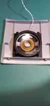
Speaker housing mounted to roof (a tight friction fit between the beams:
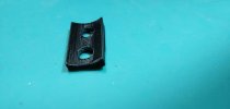
Here is the 3D printed "saddle" to mount two toggle switches on the "hump" in the cab:
Here are the toggle switches mounted on the "hump":
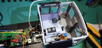
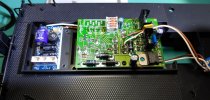
Track power to the toggle switches, soldered to back of motor block connector of direct interface:
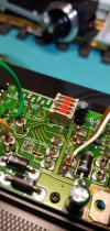
Position of dip switches and "collars" used for jumper wires to interface board:
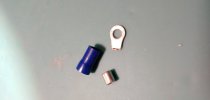
How I made the "collars":
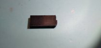
3D printed "riser block" to mount 55021 above interface board and sound decoder:
"Riser block" mounted to frame:
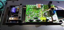
LGB 55021 mounted on riser block using Massoth PCB bracket:
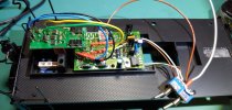
Wiring complete:
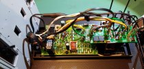
View of speaker and housing in cab:
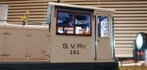
All back together again:
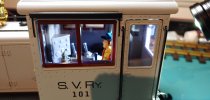
View of toggle switches in cab: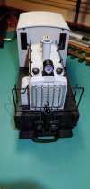
I find that if both decoders are connected to the programming track at the same time, CVs can't be read reliably, and it is best if you can disconnect one while reading the other. I knew that I would require one switch to disconnect the sound decoder. I had originally thought that the multi-function switch in the cab would disconnect the 55021 from power, but it turns out this switch has no purpose once the decoder is installed - so two toggle switches were required. I couldn't just leave the 55021 plugged onto the direct interface board since there was no way to isolate the power to it. I flipped the 55021 decoder the right way up and made jumper cables to connect all the appropriate pins to the interface, except the track power inputs which I could connect to a switch. That turned out to not isolate the decoder either, and in the end I removed all except the motor + and - jumpers to the interface. To allow the cab light to be operated with function A1 of the 55021 I did had to snip the cab light wires at their connection plug on the interface board and connect them directly to the decoder function outputs.
In retrospect it would have been simpler to remove the decoder interface entirely, but I really like the way the motor block plugs directly into the interface from underneath on this locomotive.
I'm sure others would have found much better ways of doing this, but I'll document what I did in case some of the ideas are of any use. In particular: (1) a custom, low profile speaker housing, which tucks nicely into the cab ceiling; (2) location of two toggle switches mounted on the "hump" in the cab with a custom 3d printed saddle; (3) a good way to connect a jumper wire to the sockets on the decoder interface (I tried making pins to go inside the sockets, but they were wobbly - an external "collar" is much better!, and; (4) 3D printed riser block to mount the 55021 above the interface board and Massoth S decoder.
Here are instructions to open the locomotive:
To remove the motor block:
- remove the very back screw and the second from front screw of the motor block underneath - the motor block will drop down and unplug from the interface board.
To remove the hood:
- undo the four screws (two on either side of the motor block housing underneath) - easier done with the motor block removed.
- with the locomotive the right way up, very gently pry the long rails along each side of the hood up to release the lugs which are press fit into square holes.
- turn the railings outwards towards 90 degrees from the hood to unhook them from the cab. The railing has a short 90 degree bend on the end to retain it to the cab (hint: if you look inside the cab you can see the railing ends to check their orientation).
- carefully pry the two front hand rails outwards at the top to remove the top ends from the holes next to the radiator (use a plastic tool to help pry them out if they don't come out easily).
- keep the hand rails gently pried apart to prevent the ends from scratching the hood.
- lift the back end of the hood up a bit and slide it slightly forward, then lift it clear of the chassis.
- the wires from the front headlight can be unplugged from the interface board so that the hood can be set aside.
To remove the cab roof:
- carefully remove the 4 tiny screws (2 at the front and 2 at the back). They are easy to lose!
- the cab roof should lift off
PICTURES BELOW:
Here is the 3D printed speaker housing that fits around the magnet for a low profile:

Speaker housing mounted to roof (a tight friction fit between the beams:

Here is the 3D printed "saddle" to mount two toggle switches on the "hump" in the cab:

Here are the toggle switches mounted on the "hump":

Track power to the toggle switches, soldered to back of motor block connector of direct interface:

Position of dip switches and "collars" used for jumper wires to interface board:

How I made the "collars":

3D printed "riser block" to mount 55021 above interface board and sound decoder:

"Riser block" mounted to frame:

LGB 55021 mounted on riser block using Massoth PCB bracket:

Wiring complete:

View of speaker and housing in cab:

All back together again:
View of toggle switches in cab:


