musket the dog
Registered
Hello Everyone,
If you can cast your mind back to the height of lockdown in the UK last year there was a design competition posted on the forum, the the prize being a motor block of your choosing to help bring a prospective design to fruition.
2020 Design Competition
My proposal was for a A. Horlock and Company 0-4-0, freelance but heavily inspired by the original locomotives of the Padarn Railway. Happily, one of these locomotives survives, the Fire Queen of 1848.
Fire Queen
A few years prior to the competition I had already sketched out a rough plan for the locomotive using the Autodesk CAD program. Like a 2D sketch I used the 3D CAD to roughly arrange the Hartland Mack motor block and the original wheels to check I could create something that would be vaguely recognisable as a Padarn loco but in keeping with the proportions of the rest of my stock. It had always been a bit of a 'definitely,maybe one day' project, it was part of the fictional history of my railway but not in keeping with the era I wanted to model. The competition was a good excuse to look at actually getting around to making it and to my pleasant surprise I won.
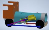
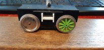
I never get around to anything quickly and so here we are over a year later beginning to make a start. Jonathan (who ran the competition) was kind enough to also supply me with a set of 58mm driving wheels for the locomotive. This required a slight redesign of the loco as originally I had planned on using a set of LGB wheels from one of their small 4 wheel motor blocks.
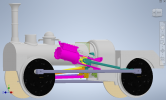
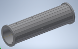
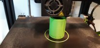
I took the opportunity to redesign most of the loco in the end. The Holock locos have been described as being 4-wheeled versions of the Crampton type. One of the features that distinguishes Crampton locomotives is that they do not have frames like a conventional loco, instead everything is bolted to the boiler like a traction engine. The bigger wheels required me to change the boiler diameter, which in turn meant that I had to modify all the other components.
The model will be tender driven by the Mack block and the engine will free wheel. Having no frames there is no convenient way to leave the valve gear out and claim that it is hidden at the same time. I have attempted to model valve gear on my scratch builds in the past but have always bottled it in the end. There's really no escaping it with this engine though and so having meticulously studied the 'Handbook for Railway Steam Locomotive Enginemen' I gave it a go. Something I can do in CAD that I can't manage in a sketch is to animate the model. If I had got something wrong by either over or under constraining the valve gear, the model will not animate. I can then also use the model to show if any of the parts are colliding into each other and need tweaking.
If you can cast your mind back to the height of lockdown in the UK last year there was a design competition posted on the forum, the the prize being a motor block of your choosing to help bring a prospective design to fruition.
2020 Design Competition
My proposal was for a A. Horlock and Company 0-4-0, freelance but heavily inspired by the original locomotives of the Padarn Railway. Happily, one of these locomotives survives, the Fire Queen of 1848.
Fire Queen
A few years prior to the competition I had already sketched out a rough plan for the locomotive using the Autodesk CAD program. Like a 2D sketch I used the 3D CAD to roughly arrange the Hartland Mack motor block and the original wheels to check I could create something that would be vaguely recognisable as a Padarn loco but in keeping with the proportions of the rest of my stock. It had always been a bit of a 'definitely,maybe one day' project, it was part of the fictional history of my railway but not in keeping with the era I wanted to model. The competition was a good excuse to look at actually getting around to making it and to my pleasant surprise I won.

I never get around to anything quickly and so here we are over a year later beginning to make a start. Jonathan (who ran the competition) was kind enough to also supply me with a set of 58mm driving wheels for the locomotive. This required a slight redesign of the loco as originally I had planned on using a set of LGB wheels from one of their small 4 wheel motor blocks.

I took the opportunity to redesign most of the loco in the end. The Holock locos have been described as being 4-wheeled versions of the Crampton type. One of the features that distinguishes Crampton locomotives is that they do not have frames like a conventional loco, instead everything is bolted to the boiler like a traction engine. The bigger wheels required me to change the boiler diameter, which in turn meant that I had to modify all the other components.
The model will be tender driven by the Mack block and the engine will free wheel. Having no frames there is no convenient way to leave the valve gear out and claim that it is hidden at the same time. I have attempted to model valve gear on my scratch builds in the past but have always bottled it in the end. There's really no escaping it with this engine though and so having meticulously studied the 'Handbook for Railway Steam Locomotive Enginemen' I gave it a go. Something I can do in CAD that I can't manage in a sketch is to animate the model. If I had got something wrong by either over or under constraining the valve gear, the model will not animate. I can then also use the model to show if any of the parts are colliding into each other and need tweaking.

