55022 Decoder Lighting

dunnyrail

DOGS, Garden Railways, Steam Trains, Jive Dancing,
Staff member
GSC Moderator
Country flag
Track Powered Loco on DCC
Have fitted the 55022 to a small loco with the 4 Track/Motor wires sorted, now fitted lights with 5v LGB bulbs to common return pad and the other 2 wires to pads Forward and Reverse light pads. As ever the LGB DC tables somewhat confusing still.

Set as follows with no lights, speed steps on Massoth Handset at 28.
cv49=5
cv50=5
cv51=0
cv52=128 unchanged
cv53=64 unchanged
Think my issue could be with 52 and 53 but hm not at all sure. As ever HELP!
 
Is your common return the pos or neg. It should be the positive.
 
Is your common return the pos or neg. It should be the positive.
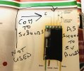
Thanks for quick responce, nothing about pos or neg in the instructions but with LGB 5v bulbs not relavent? Below what I have done. I think the not used one may be for the cab light?

CF3A7344-A9D6-47FE-A7A7-8EC0C5CED56A.jpeg
 
cv49=5
cv50=5
cv51=0
cv52=128 unchanged
cv53=64 unchanged
Think my issue could be with 52 and 53 but hm not at all sure. As ever HELP!

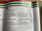
CV 49 F1 divider value
CV 50 Light o/p divider value
CV 51 F1 command key - would normally be '7' if F1 used to switch smoke.
CV 52 Command lights fwd. - 128 is correct
CV 53 Command lights rev. - 64 is correct

For 28 speed steps, CV 29 should be:
2 (no analogue) or 6 (with analogue)

I would check the value of CV 29..

PhilP.
Phillip looks like you have nailed it value of 4 currently I think, think 6 will do it!. Many thanks will try it in the morning.
 
The default on these decoders is 14 speed steps. Check CV29 if it is 4 its 14 speed steps,
I think you need CV = 6 for 28 speed steps
 
From the pic in post #3 looks like you've got F1 as the common return. I don't have a labelled wiring diagram but shouldn't "Not used" (the pad between rear lights and F1) be the common return?
 
From the pic in post #3 looks like you've got F1 as the common return. I don't have a labelled wiring diagram but shouldn't "Not used" (the pad between rear lights and F1) be the common return?
Thanks for your reply. Hm you tell me, as I read the diagram there are 3 possibilities for lights with the 2 used and one unused pads being for lights and the joint back to F1 pad completing the circuit. Would love to know the correct answer. If the lines from F1 are not correct then the diagram was and still is clearly misleading, not an unknown phenomenon with chip instructions.

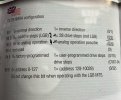
Responding to Mike (Dutchelm) again thanks. Will try that in a while. Here are the nites in the manual for 55022, about as user antagonistic as anything could be! “1=28 drive steps (not LGB) (0/2)” fascinating use of confusion.
552753B9-F091-40FF-A5E0-B18A2730D70F.jpeg
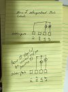
Oh I think I get it now, look at my amendments below showing requirement for the bits!
03050CF7-C62A-4541-998E-07B1A82692F3.jpeg
 
Last edited:
I can't use 'reply', or quote text at the moment..

In reply to Phil2um's wiring query:

No, the diagram is correct.. It shows the front and rear lights from their outputs through the bulbs to the common, AND it shows whatever the 'F1' load is, also going back to the common..

Regarding the 'common':
In the DCC way of doing things, the 'common' return is 'decoder +ve. - All the light and function outputs, switch to ground, when 'on'.

PhilP.
 
Hi Jon and Phil

I was not questioning the correctness of LGB's diagram. I was just responding to the way Jon has labelled his connections on the diagram. He has an arrow pointing to F1 calling it "Com to 5V bulbs" and another arrow pointing to the node which I presume to be the connection to the decoder Ve+ pad calling it "Not used".

If I understand Jon's original post he has no load connected to F1 therefor this should actually be "not used" in post 3 and the node connected to the Ve+ solder pad should be "Com to 5V bulbs".

If the decoder is wired the way Jon has it labelled, i.e. no connection to the Ve+ pad, that explains why he has no lights!B 2083 - 1 _1_.jpeg

Ve+ is the "common return"!
 
Last edited:
Hi Jon and Phil

I was not questioning the correctness of LGB's diagram. I was just responding to the way Jon has labelled his connections on the diagram. He has an arrow pointing to F1 calling it "Com to 5V bulbs" and another arrow pointing to the node which I presume to be the connection to the decoder Ve+ pad calling it "Not used".

If I understand Jon's original post he has no load connected to F1 therefor this should actually be "not used" in post 3 and the node connected to the Ve+ solder pad should be "Com to 5V bulbs".

If the decoder is wired the way Jon has it labelled, i.e. no connection to the Ve+ pad, that explains why he has no lights!View attachment 273212

Ve+ is the "common return"!
Thanks Phil that was exactly how I wired it up so looks like I need to change it to wot you have so kindly drawn for me. Thus Ve is plus the other two (LR LF) are return or neg. Not what I understood the diagram to say clearly. So what is F1 for? Another light say cab light? Will not be changing the chip as it is in a loco that I never want to face pulling apart again, but have another to use and one that would be easy to fit lights to.
 
What might help is front and rear lights are normally defaulted to F0, not F1.... both of them from the same function but in reality the chip also decides when the loco is going forwards or backwards. These 2 "outputs" are never connected to anything except a lamp and then to common.

You as a rule never connect a function "output" to another function "output". (I use quotes since old school would call them inputs)

Greg
 
So what is F1 for?
The "F1" in the LGB diagram is a generic representation for any other load you might want to hook up as long as it does not exceed the current (mA) capacity of the pad. It could be a cab light or maybe even a smoke unit. The current limits should be in the decoder manual somewhere. Whatever load is hooked up to the pad will be switched on and off by the F1 key/button on your controller/central station. My guess is it is set be on continuously and active in both forward and reverse by default when turned on.
 
Last edited:
One other thihng to be aware of! The output of light function pads are probably set to full decoder voltage and your 5V bulbs will quickly expire. I'd put 18 or 24V bulbs in initially just as a precaution. If they are real dim then you are probably safe putting the 5V bulbs back in.
 
One other thing to be aware of! The output of light function pads are probably set to full decoder voltage and your 5V bulbs will quickly expire. I'd put 18 or 24V bulbs in initially just as a precaution. If they are real dim then you are probably safe putting the 5V bulbs back in.

Edit added:
Just checked the manual - The factory default output voltage of both the lighting terminals and the F1 terminal is full decoder voltage full rectified track voltage. CV 49 (F1) = 32 and CV 50 (both lighting terminals) =32. The manual recommends setting these to 5 for direct connected 5V bulbs. See pg 23 of the manual. Also the current load limit is identical for both lighting terminals and the F1 terminal. The limit is 0.1A or 100 mA. Therefore no smoke unit! See manual pg. 36.

Another edit added: changed to Greg's more correct decoder output voltage terminology.
 
Last edited:
The "F1" in the LGB diagram is a generic representation for any other load you might want to hook up as long as it does not exceed the current (mA) capacity of the pad. It could be a cab light or maybe even a smoke unit. The current limits should be in the decoder manual somewhere. Whatever load is hooked up to the pad will be switched on and off by the F1 key/button on your controller/central station. My guess is it is set be on continuously and active in both forward and reverse by default when turned on.
Thanks again for further clarification and to others that now make things crystal clear to me. I had updated the CV to push 5v out to the lamps. Now I probably Need to face pulling the loco apart again to see that things work as predicted.
 
Now I probably Need to face pulling the loco apart again to see that things work as predicted.

If things work as expected, you will not need to take it apart.. If you made a wiring error, then you will.

You have already set the lighting voltage divider, so should be fine with your 5V bulbs..

PhilP.
 
When 'tuning' the cv's for LGB lights, I find that my Zimo system is too bright at a 5 entry. I set these to 4. LGB takes V+ and divides it by the number plugged in. Since my DCC system outputs 24 volts, the bulbs are too bright. ON a system with lower command station voltage the 5 entry is best.
 
Back
Top Bottom