3D printed Electric Decouplers

Dagnall

Registered
17 May 2016
34
15
71
HAYLING island
Best answers
0
Country flag
Hi I was wondering of anyone else is interested in 3D printed electric de-couplers, or is it just me? :)

During these "interesting times", I have been revisiting my servo driven LGB "hook and loop" decoupler, to see if I could improve it by using tiny geared stepper motors.
I did post some initial stuff in another forum here , but I have had some success with a new design and was wondering of anyone else is interested..
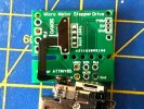
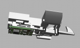
the CAD section shows the anticipated final version with the motor drive on a small integral PCB (work in progress!).
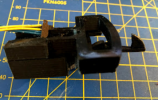
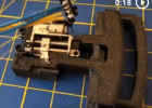
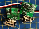
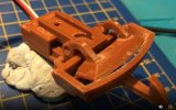
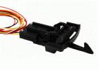
The actual ones in the other photo shows the 3d printed parts, the gear motor drive unit and the completed test unit.
1613838616744.png1613838876910.png1613838912557.png
I have used plastic (printed) springs for the hook (up/down) spring, and these are only active when the unit is "coupled". A magnet now provides centralization for the hook, so it can go sideways.
When you want to decouple, the "pusher" bar is forced forwards (like the massoth design), and disconnects any engaged hook, and at the same time releases the "up down spring" so the couplings own hook can go down and disengage.

I will put it on thingyverse when I'm satisfied.

BUT the reason for the post is to ask if anyone else is interested ? -
I actually use knuckle couplings on my railway here, so actually have not much incentive to progress further now I have proved the concept to my satisfaction.
??? BUT if anyone else is interested, I would love to hear from you .. and it will encourage me to keep improving the design - and hopefully discuss what improvements can (/ need ? ) be made!

Electronics:
I have designed a tiny PCB for this project, but have not made it yet, so the motor is wired in the photos. . I will build the SMD board when the bits arrive.
The board takes a standard RC servo PWM signal and uses it to make the stepper drive go from one end stop to the other.
(I have another version of the code that gives "analogue" drive, so if anyone is interested in it for other applications, let me know ., but that is for another post.. )

Little video of an earlier prototype to show the principle of operation

Cheers
Dagnall


1613838616744.png1613838876910.png1613838912557.png
 
  • Like
Reactions: 1 users

PhilP

G Scale, 7/8th's, Electronics
5 Jun 2013
33,562
3,521
Nottingham
Best answers
0
Country flag
Well I am interested..

The Massoth units are a little finnicky, and can be a bit of a pain.

PhilP.
 

FatherMcD

Registered
13 Mar 2014
382
35
Idaho
Country
United-States
Best answers
0
Country flag
Yes, definitely interested. I need to make something to justify the 3D printer purchase!
 

3 minutes of fame

3d printing, electronics and trams
14 Dec 2020
574
154
Lincolnshire
www.mgnr.uk
Best answers
0
Country flag
Thanks Dagnall Dagnall . I use your knuckle couplers as I think they are neater. I build all my own stock, so I have a different outlook to enthusiasts who favour ready to run, so I am sure that the automatic LGB couplers have a place for those with extensive stock, but would like to do a little more shunting and uncoupling.

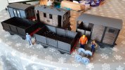
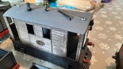
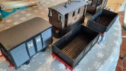
I've been shamelessly downloading and building many of your designs off thingiverse, including the tram and wagons. Pictures below of work so far!

I'm working on a Wisbech and Upwell coach at the moment and have used some of your designs such as buffer beams and axle boxes. I hope to be finalising the files in the next week, and will then upload and share.
20210217_130438.jpg20210217_130458.jpg20210217_130513.jpg
 

Dagnall

Registered
17 May 2016
34
15
71
HAYLING island
Best answers
0
Country flag
PhilP PhilP FatherMcD FatherMcD 3 minutes of fame 3 minutes of fame
Many Many Thanks for the encouragement!..
I will continue the development with added enthusiasm!

The knuckle couplers are pretty good, but they do not have worse cross track misalignment tolerance than the hook and loop, so automatic recoupling is a bit hit and miss. - But then I rarely actually "shunt".

The original hook and loop design was part of an attempt to have an end to end line automatically decouple the loco and then have another loco take over for the way back - but that whole idea got abandoned, and I just made the garden track a full loop!.

I will keep you all informed of progress.. FYI, I am planning on getting some PCB's for the servo electronics, - I will look into how much it would cost to have them fabricated with all the components soldered.

D
 
  • Like
Reactions: 1 user

The Shed

Citizen of the Republic of the North East.
8 Mar 2020
1,070
238
Darlington, County Durham.
Country
England
Best answers
0
Dagnall Dagnall , my handiwork from way back in 2017!...Always worth a mooch at your latest incarnations!:)

Revised G Scale LGB Servo Coupling.PNG
 

Dagnall

Registered
17 May 2016
34
15
71
HAYLING island
Best answers
0
Country flag
The Shed The Shed
Thanks.. I am very grateful for the encouragement!..

I was going to stop the current stepper motor development for the hook version, but have found new enthusiasm.!.

In short.. it works.. and the stepper motor is much more powerful than the nano servo, so I can use a simplified,3D printed, spring design based on the standard plastic spring.
This video is just for my record., but shows the concept works..

The "sharks fin" needs to be carefully sanded, and the horrid "pillar" that deflects the spring needs work.. but I got about 2-3 Oz force to "open the hook far enough to decouple with this configuration. My "Heyn" version with the same spring gives about 0.75, so I can probably reduce the pillar significantly (which should improve everything).

Also, for anyone else interested.. I have ordered some prototype (unpopulated) PCB for the stepper drive. and found out PCB way should be able to do them assembled and perhaps programmed for bout £5 a board in small but significant volumes. -- Not sure about VAT/duty and shipping..
Last time I got stuff from China (JLPCB SMD assembled boards for my SMD versions of Rob's Rocrail WIO boards) , Shipping and VAT and duty were more than the board and component costs!. ..

they looked nice though!. IMG_4199[1].JPG
D
 

Dagnall

Registered
17 May 2016
34
15
71
HAYLING island
Best answers
0
Country flag
Updates for anyone interested!!. These are my JLPCB made pcb prototypes:
Screenshot 2021-03-26 132428.jpg
I got this initial PCB design up and running, and it works great. The tiny SOT23 motor drivers do not get hot.
programming is via the ICP socket using a programmer iand s a doddle.
Soldering the film wire on the back was "interesting" as the alignment marks were hidden on this original design!.


I have since updated the PCB design to have better alignment marks for the film wire , and these arrived from PCBway today..
I have not populated them yet!..

I have published the code and PCB files at Github
A little video of the units working is here -- You may notice that I have made the code so that, for testing, you can add a 100k resistor from reset to ground to switch to "analogue" mode. Personally I think this is bit "gritty", but some may find it useful.
Once programmed and working to your satisfaction, , you can snap off the ICP part making a very small PCB...

On this PCB, I discovered a small error in that snapping broke a crucial connection, and so redesigned the pcb and sent of for some more.. only to realise the servo connections were "wrong" for the sparkfun micro servo connections.. DRAT- PCBWAY had made the boards before I noticed this.. so I just waited to get them so I could also check out the revised silkscreen to align the film wire better..
.Screenshot 2021-03-26 135922.jpg

I do not have a sample of the FULLY" revised PCB "V2" that has the corrected servo pinout, but I have added the (latest) PCB design as a "project" at PCBWAY, and you may be able to order them assembled with all parts , If you do, apparently I get a tiny amount of credit to allow me to make more pcbs!

But if you want them sourced and assembled, I would suggest omitting the "sparkfun" cable assembly.. it turned out to be quite expensive compared to the rest of the parts. and you can always solder on your own!

JLPCB have also given me great service in the past, and the design is compatible with their assembly and sourcing from LCSC.. The only thing I would mention is that its best to use DHL or Fedex, The cheaper postal delivery I used for the prototype took nearly two months of anxious waiting.. Fedex was about 10 days from order to delivery. DHL do a service that includes VAT and duty, so prevents worries about customs.

At time of writing the project shows as "under review" at PCBWAY, but hopefully it will get approved soon..
 

dunnyrail

DOGS, Garden Railways, Steam Trains, Jive Dancing,
Staff member
GSC Moderator
25 Oct 2009
26,169
4,993
75
St.Neots Cambridgeshire UK
Best answers
0
Country flag
Thanks Dagnall Dagnall . I use your knuckle couplers as I think they are neater. I build all my own stock, so I have a different outlook to enthusiasts who favour ready to run, so I am sure that the automatic LGB couplers have a place for those with extensive stock, but would like to do a little more shunting and uncoupling.

I've been shamelessly downloading and building many of your designs off thingiverse, including the tram and wagons. Pictures below of work so far!

I'm working on a Wisbech and Upwell coach at the moment and have used some of your designs such as buffer beams and axle boxes. I hope to be finalising the files in the next week, and will then upload and share.
View attachment 281036View attachment 281037View attachment 281038
I have gone down the route of couplings and found that LGB type are the most durable and reliable in G. Plus shunting with them by hand close up is perfect. But and there is always a but, when you are making all from scratch then there may be other options. In your case 2 come to mind, 3 links are easy to make and with double buffers are just the job. Tight curves can be an issue but so long as there is sufficient straight on a crossover or after a point then few problems are encountered. I speak from experience having used 3 links in 0 gauge on 2’6” radius curves. Another option may be to look at the Bemo type, quite small and can be easily converted to magnetic uncoupling. Sure you could knock some up in G, though the hooks may be a challenge but bent wire a possibility for a modest fleet.
 

Dagnall

Registered
17 May 2016
34
15
71
HAYLING island
Best answers
0
Country flag
I have gone down the route of couplings and found that LGB type are the most durable and reliable in G. Plus shunting with them by hand close up is perfect. But and there is always a but, when you are making all from scratch then there may be other options. In your case 2 come to mind, 3 links are easy to make and with double buffers are just the job. Tight curves can be an issue but so long as there is sufficient straight on a crossover or after a point then few problems are encountered. I speak from experience having used 3 links in 0 gauge on 2’6” radius curves. Another option may be to look at the Bemo type, quite small and can be easily converted to magnetic uncoupling. Sure you could knock some up in G, though the hooks may be a challenge but bent wire a possibility for a modest fleet.
Thanks dunnyrail..
It's interesting you mention shunting and tight raidii.. The only reason (apart from oncoming insanity!) that I have been further exploring these LGB types is that I still have an un scratched itch to do some automated uncoupling and coupling, And the side to side coupling tolerance on my knuckle couplers is a bit too small to get correct alignment if you have "random" coupling to do-with carriages or waggons with "turning bogies"- which can easily get "misaligned".. My knuckle couplers are fine if you just uncouple and then recouple, but I would rather like to have the ability to switch locos automatically when they get to the terminal..
The other experiment I want to do is to see if I can keep my Nuquida long coach on the rails around the R1 curves of my layout!. They were a present, and are now fitted with better metal wheelsets, but have never run properly behind my bachmann percy, who pulls them off the track at the first corner. I was hoping that the hook and loop might have a better angle of pull. I really should quickly set this experiment up- I have way too many "almost right" 3d printed hooks and loops!. - But I have been concentrating on some tiny details on the design- e.g last bit was the discovery of two screws on the Stainz front connector that I did not allow for - so I have just sculpted some bits to avoid having to file them!.
 

dunnyrail

DOGS, Garden Railways, Steam Trains, Jive Dancing,
Staff member
GSC Moderator
25 Oct 2009
26,169
4,993
75
St.Neots Cambridgeshire UK
Best answers
0
Country flag
Thanks dunnyrail..
It's interesting you mention shunting and tight raidii.. The only reason (apart from oncoming insanity!) that I have been further exploring these LGB types is that I still have an un scratched itch to do some automated uncoupling and coupling, And the side to side coupling tolerance on my knuckle couplers is a bit too small to get correct alignment if you have "random" coupling to do-with carriages or waggons with "turning bogies"- which can easily get "misaligned".. My knuckle couplers are fine if you just uncouple and then recouple, but I would rather like to have the ability to switch locos automatically when they get to the terminal..
The other experiment I want to do is to see if I can keep my Nuquida long coach on the rails around the R1 curves of my layout!. They were a present, and are now fitted with better metal wheelsets, but have never run properly behind my bachmann percy, who pulls them off the track at the first corner. I was hoping that the hook and loop might have a better angle of pull. I really should quickly set this experiment up- I have way too many "almost right" 3d printed hooks and loops!. - But I have been concentrating on some tiny details on the design- e.g last bit was the discovery of two screws on the Stainz front connector that I did not allow for - so I have just sculpted some bits to avoid having to file them!.
One of the things with the Newquida coaches is that they are very light and metal wheels help in this respect which somewhat curtails the fact that the coaches and indeed wagons are a good cheep option. The oither problem with them is that the bar from the bogie that the coupling is mounted on has very bendy plastic making them at time almost impossible or at best difficult to uncouple which is why I sold out all my Newquida coaches except for one. And that one hardly gets used but it was fitted with expensive Troeger transfers from Germany.
 

Dagnall

Registered
17 May 2016
34
15
71
HAYLING island
Best answers
0
Country flag
One of the things with the Newquida coaches is that they are very light and metal wheels help in this respect which somewhat curtails the fact that the coaches and indeed wagons are a good cheep option. The oither problem with them is that the bar from the bogie that the coupling is mounted on has very bendy plastic making them at time almost impossible or at best difficult to uncouple which is why I sold out all my Newquida coaches except for one. And that one hardly gets used but it was fitted with expensive Troeger transfers from Germany.
I tried the latest decoupler prototypes on the Stainz and the Nuquida .. My Nuquida have metal wheels, so roll really easily.. But they do not have enough friction to properly complete the "decouple dance".. Result, the "coach" hook stays engaged firmly on the Loco loop, and the decoupler bar cannot push it down out of the way, as its "properly" hook shaped!. GRR!!.

I also used the hook and loop coupling and drove the coach around part of the track that works fine for the normal small LGB coaches and my knuckles, and it fell over on the curve.. - The track really is not that bad!. I will put that down to the weight being too high,, and too little..
. I'm going to give them to my brother in law who only uses R2 or bigger curves!.

I will now bag all the aborted 3D prints of the various versions of the Hook and loop decoupler to tidy my desk, and re-instate my "electric Knuckle" decoupler on the Stainz, but this time with the decouple lever being pulled by the stepper motor drives.. No uploads to thingyverse for this version - as I think this is a bit "niche!" .

If I get really bored, I may look at seeing if the Stepper Motor can be configured nicely to work with my "3d printed Heyn" copy I designed, but I am not holding out much hope. It would probably be easier just to use a standard servo for most locos-

Cheers
Dagnall
 

Dagnall

Registered
17 May 2016
34
15
71
HAYLING island
Best answers
0
Country flag
Short answer..
I did get very bored.. ;)
BUT The stepper motor works surprisingly well in the "HEYN" design!.

Screenshot 2021-07-24 172426.jpg
Attached zip includes a video that I do not want to share on Youtube as yet.
To bring you up to date.. I spent a very long time adjusting this design, and happened to chat to a guy in Germany who suggested it would make an excellent Injection moulded coupler, and that he wanted to investigate costs etc. So I agreed to let him see if he can do this economically, and also agreed that I would not publish this design on thingyverse for a while, so that he can get some return on investment if the injection moulding project goes ahead. We have not spoken for a couple of months, so it is possible the mould costs were exorbitant, but I will hold off publishing until I hear from him..
If the project goes ahead, I think he will supply the parts, stepper motor drive, and a small pcb to hide in the loco.

Cheers
Dagnall
 

Dagnall

Registered
17 May 2016
34
15
71
HAYLING island
Best answers
0
Country flag
dunnyrail dunnyrail and 3 minutes of fame 3 minutes of fame
Its been a long time but I wanted to bring you all up to speed!
The "Guy in Germany" that I mentioned is Marcus at MD electronics, and he has had moulds made so that the decoupler is now available as a proper plastic moulded device.
He has designed a small PCB that takes DCC power and gives a very easy interface to control the unit's stepper motor. This electronics is quite sophisticated and can be programmed using CV's as one option is for it to be a separate DCC decoder.

This is the link if anyone needs these: (Elektrischer Entkuppler (Einheit) für Spur G analog + digital/DCC SET - MD-ELECTRONICS)
Apart from the initial prototypes he sent me I do not get any "cut" from this. Marcus is a small one man operation just starting out, and he has quite a lot of interesting products.

All the very best and a happy new year 2022.
Dagnall
I think you can see the family connection to the brown version I posted!


Screenshot 2022-01-08 164849.gif
 

PhilP

G Scale, 7/8th's, Electronics
5 Jun 2013
33,562
3,521
Nottingham
Best answers
0
Country flag
I can 'see' both your posts.

An interesting project, and I have made a note..

PhilP