27180 Le Corpet Louvet smoke connection to PCB ?

Rackman

Registered
7 Feb 2012
14
0
Best answers
0
Hi,
I've had a grey Le Corpet Louvet for many years - no smoke unit.
When passing a well known emporium some years ago, I bought a smoke unit to retro-fit but when I opened the loco I was presented with a pcb with four potential pins to connect to. A call to the shop produced zero help or interest !
I have finally decided to do something about it so HELP !!!!!

There is nothing that shows the connections on the service sheet or the info with the loco oddly.

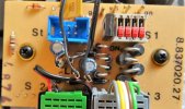
The pcb has four vertical pins with small lettering that reads.................

ge ws br (partly obscured but could be hr) gn

The leads on the smoke unit are one white and one black, so I am guessing its white to ws and black to br - am I right ?

Any help much appreciated.
Thanks
Paul
 

Gizzy

A gentleman, a scholar, and a railway modeller....
26 Oct 2009
36,138
2,273
63
Cambridgeshire
www.gscalecentral.net
Best answers
0
Country flag
Those are the terminals for the motor Paul.

ge is yellow (gelb in german), ws is white (Weiss), br is brown (braun) and gn is green (grun).

Are there any terminals marked Dampf on the PCB? Maybe next to the ones for the head lamp.

You will also need to know if your smoke unit is 5 Volts or 18 Volts....
 

Rackman

Registered
7 Feb 2012
14
0
Best answers
0
Hi Gizzy,
that was fast !
I once saw someone elses car wiring loom go up in smoke - and I did not want to join the club - good job it seems.
No - nothing with Dampf and no other spare terminal pins either.

I mentioned this issue to a different shop last week and they were surpised that Le Corpet Louvet from 2001 would not have smoke as standard.

What I can see are the terminal pints that the headlights are routed to - so can I solder them onto the headlight tags ?
I popped the smoke unkit into the stack years ago and no longer recall whether 5 or 18 volts although the emporium concernd are a main dealer and SHOULD have given me the correct item (hmm)
Paul
 

Rackman

Registered
7 Feb 2012
14
0
Best answers
0
Just followed your link and its definitely a 5 volt unit with black and white wires
Paul
 

Gizzy

A gentleman, a scholar, and a railway modeller....
26 Oct 2009
36,138
2,273
63
Cambridgeshire
www.gscalecentral.net
Best answers
0
Country flag
Looking at the Stainz post, black and white wires are either a 5 Volt unit or 24 Volt if DCC.

I would wait for others to reply and advise, who have had more experience than I in wiring up a Corpet....
 

stockers

Trains, aircraft, models, walking, beer, travel
24 Oct 2009
25,631
3,795
65
Nr. Ashford, Kent. England.
Best answers
0
Country flag
Dont put it on the light terminals. The power demand of the smoke unit is too great for this output.

Black and white wires indicate a 5 volt unit for connection to a loco with voltage stabilizing circuitry.
(18 volt wires are grey and black)( or orange/brown)
(24 V are both white)
 
Last edited:
D

Deleted member 1986

Guest
From memory can recall several versions of this PCB knocking around that were factory fitted, a picture would help...?
 

Zerogee

Clencher's Bogleman
25 Oct 2009
17,351
1,723
North Essex
Best answers
0
Country flag
.........
ge is yellow (gelb in german), ws is white (Weiss), br is brown (braun) and gn is green (grun)........

Just to add to Gizzy's decoding of the four wire/pin colour codes: the brown and white connections (br and ws) are the ones coming from the track pickups, so they supply track power; the green and yellow (gr and ge) are the ones to the motor terminals. So if you want to pick up track power at full track voltage for any reason, then the brown and white labelled pins are where it comes in.
An older 3-wire (pre-Digital, pre-MTS) motor block will not have the yellow (ge) pin or wire.

Jon.
 

PhilP

G Scale, 7/8th's, Electronics
5 Jun 2013
33,561
3,521
Nottingham
Best answers
0
Country flag
As stated, there are several board versions.. We really need a photo..
 

Rackman

Registered
7 Feb 2012
14
0
Best answers
0
Hi guys, photo as requested
 

Attachments

  • DSC01539 (3).JPG
    DSC01539 (3).JPG
    109.9 KB · Views: 0
D

Deleted member 1986

Guest
Option One: Tap wires from ws & br, via switch to a 5v regulator board, and then onto smoke unit.
Example for what to look for:
http://www.ebay.co.uk/itm/L7805-Lm7...152209?hash=item58f1c21bd1:g:61sAAOSwKOJYHXCw

PCB 1.JPG


Option Two: Bit of detective work required to find the positive and negative outputs, helpful pointers Zener Diode as circled, the two capacitors which are polarised, stripe down one side is the negative, diagram for bridge rectifiers, larger set of diodes are 3 amp and for motor control, use the smaller set which are 1 amp for the lights, looking for the pairs with the silver bands pointing downwards, one pair will be the input from ws or br, the other will be the positive output, other end of pairs of diodes will reveal the negative, tap these from underneath, run positive via switch then onto 5v regulator, then onto smoke unit.

Example of what to look for:
http://www.ebay.co.uk/itm/L7805CV-5...262642?hash=item3d3650aff2:g:948AAOSwB-1YpxQG

PCB 2.JPG


Option Three, as above, substitute 78xx for a DC to DC Buck Convertor.

Example for what to look for:
DC to DC Buck Converter
http://www.ebay.co.uk/itm/Mini-360-...340218?hash=item237b1ccc3a:g:lj4AAOSwEzxYc3Hs

OR

http://www.ebay.co.uk/itm/DC-DC-Adj...819736?hash=item36090903d8:g:zm4AAOSwvt1WRCJb

PCB 3.JPG


Later revisions of the PCB had a connection for a smoke unit, as none appear on this particular PCB, it is probably safer to avoid "tapping" the connections for the Zener Diode, the smoke unit pulls about 260mA, plus 33mA times the number of bulbs, don't think the Zener is of sufficient wattage to support the additional load of a smoke unit.

Options One and Two use linear voltage conversion, extremely wasteful, as excess voltage is given of as heat, they will get warm!
Option Three, about 96% efficient with the voltage conversion and no heat!

Option Four:

If bewildered, and looking to the sky for inspiration fails , plonk it in a jiffy bag to moi!
 
Last edited by a moderator:

Rackman

Registered
7 Feb 2012
14
0
Best answers
0
Hi Arthur,
a huge thank you for a stunning response - mostly written in Greek but none the less, I haven't seen anything that good since the car manual......How to Keep Your Beetle Alive- for the Complete Idiot

OK - I'm going for option 1 and the voltage regulator is now winging its way from China for the princely sum of £1.11p post free - how can they do that ???

Can you recommend a suitable switch ?
Is a slide switch better, so it doesn't snag if sticking out of the bottom of the loco ?
Is there an optimum switch location ?

Paul
 
D

Deleted member 1986

Guest
If you have a Maplin store nearby pop in and have a look at this one...

http://www.maplin.co.uk/p/ultra-miniature-toggle-switch-spst-fh97f

Attending GRAIL?, Squires Tools will have a variety of switches that you can have a look at.

Where to fit........ needs to accessible to be able to turn it on/off and where you can get the wires to it!!!!!
Round hole is easier to drill than cut out an oblong................

Backhead plate of boiler moulding, cab floor, lower rear of the buffer beam......can always paint it black to make it appear less obvious..............
 

Rackman

Registered
7 Feb 2012
14
0
Best answers
0
Squires is nowhere near me, so Maplins it is - I see three terminals - do I assume I use left and right ones? just being healthily overcautious as I don't want to fry anything.
Again much appreciate the excellent help - thanks Arthur
Paul
 
D

Deleted member 1986

Guest
Use the middle terminal as the IN (br) and either one or other of the two outer terminals to the voltage regulator.
The middle terminal is connected to which ever the outer terminal is opposite from the switch been thrown.
 
Last edited by a moderator:

Rackman

Registered
7 Feb 2012
14
0
Best answers
0
Think I follow that Arthur - I'll let you know if it all went OK when the voltage regulator arrives from China.
Once again, many thanks
Paul
 

Rackman

Registered
7 Feb 2012
14
0
Best answers
0
Hi,
first test report but I have a problem !
Test conditions........
100 foot circuit, track cleaning loco run round three times and then two circuits with the Le Corpet.
Small quantity of smoke oil added - loco run at 70% speed and immediately I get smoke after 20 feet of travel.
Loco returned to start and more smoke oil added - run - zero smoke. even after 4 circuits at 90% speed.
Assume I have over-filled, so reduce the amount of oil by half and run another four circuits - zilch.
Reduce smoke oil to minimal, run another four circuits - zilch,
Touch test the top of the smoke unit - ouch (I have delicate pinkies) its certainly hot.

So I am baffled.
The smoke oil is admittedly very old - but initially produced smoke. Its recently worked ok in two other locos.
Any bright ideas as logically I can't imagine what might be wrong !!!!!!

Thanks for any help
Paul