0v or +5v

collectors

Registered
16 Apr 2022
270
11
67
Norfolk UK
www.chrismorris.co.uk
Best answers
0
Country flag
Is there an advantage to 0v switching ? IE: if i had a long run of cable there may be a volt drop with 5v. Would this not be a problem with switching 0v.
 

PhilP

G Scale, 7/8th's, Electronics
5 Jun 2013
33,461
3,505
Nottingham
Best answers
0
Country flag
Is there an advantage to 0v switching ? IE: if i had a long run of cable there may be a volt drop with 5v. Would this not be a problem with switching 0v.
The voltage drop is due to the resistance of the cable, and the current you are drawing..

V=IxR Ohm's law.

Hence we recommend larger cross-sectional cables for higher current. - Less resistance, so less voltage-drop, for a specific current.

You 'see' the same effect looking for a bad joint in your track..
A good meter will show 'full' track voltage, because a meter needs a very small current to register a voltage.
You only 'see' the voltage drop across the bad joint, when you are drawing a significant current.

Example :

5V supply, long run of cable 4 Ohms.

If your load at the end of the cable draws 1A,then Ohm's law gives a voltage drop at the load-end of;

1(amp) x 4(ohms) = 4Volts

If you are only drawing 100mA (0 1A) then the voltage drop is;

0.1(amp) x 4(ohms) = 0.4Volts

In the real-world, the resistance of your cable will be very small, and (for controls and lighting) possibly only a few Amps.

It is probably 'better' to run heavier cables, with a higher voltage, as an accessory power-bus.
Then use local regulators, to give you a local supply for the accessories.

PhilP
 

collectors

Registered
16 Apr 2022
270
11
67
Norfolk UK
www.chrismorris.co.uk
Best answers
0
Country flag
The voltage drop is due to the resistance of the cable, and the current you are drawing..

V=IxR Ohm's law.

Hence we recommend larger cross-sectional cables for higher current. - Less resistance, so less voltage-drop, for a specific current.

You 'see' the same effect looking for a bad joint in your track..
A good meter will show 'full' track voltage, because a meter needs a very small current to register a voltage.
You only 'see' the voltage drop across the bad joint, when you are drawing a significant current.

Example :

5V supply, long run of cable 4 Ohms.

If your load at the end of the cable draws 1A,then Ohm's law gives a voltage drop at the load-end of;

1(amp) x 4(ohms) = 4Volts

If you are only drawing 100mA (0 1A) then the voltage drop is;

0.1(amp) x 4(ohms) = 0.4Volts

In the real-world, the resistance of your cable will be very small, and (for controls and lighting) possibly only a few Amps.

It is probably 'better' to run heavier cables, with a higher voltage, as an accessory power-bus.
Then use local regulators, to give you a local supply for the accessories.

PhilP
Sorry, What i should of said, if i have a 5v relay with the choice of 5v or 0v to energise the coil & lets say it was 500 meters cable length, the 5v might struggle, with 0v switching would this not be effected.
 
8 Mar 2014
7,806
972
San Diego
Country
Armenia
www.elmassian.com
Best answers
0
Country flag
So, maybe you can explain what you mean by 0v?

Are you meaning that the "smart end" is an open collector transistor that "pulls to ground" when energized? If so, there HAS to be +voltage some where else... and both ends would need a common ground.

From an electronic engineers point of view, it's more dependent on the transistors that are doing the switching, and the load that could cause voltage drop, and really it is the same.

Perhaps you could be a little more descriptive of what you are switching, and your two different scenarios.

Greg
 

collectors

Registered
16 Apr 2022
270
11
67
Norfolk UK
www.chrismorris.co.uk
Best answers
0
Country flag
I have a relay that with the moving of a jumper it can be energised with 5v or 0v, my choice. Are you saying it wont make any difference which way i choose as there will still be a volt drop. This is just to energise the relay coil
 

Paul M

Registered
25 Oct 2016
11,789
1,687
60
Royston
Best answers
0
Country flag
Energised with 0 volts? Sorry I'm obviously missing something
 
8 Mar 2014
7,806
972
San Diego
Country
Armenia
www.elmassian.com
Best answers
0
Country flag
No, I'm still not getting through.

One side of the relay coil is got plus 5 volts, and the other side, ground (maybe you are calling 0 volts).

0 volts makes no sense unless it is referenced to something, for example a hamster is 0 volts.

Kidding aside, voltage has to be present, and current needs to flow.

how about showing a picture of the relay, or a part number or a circuit schematic?

perhaps this is a "solid state" relay?

Greg
 
  • Like
Reactions: 1 user

collectors

Registered
16 Apr 2022
270
11
67
Norfolk UK
www.chrismorris.co.uk
Best answers
0
Country flag
No, I'm still not getting through.

One side of the relay coil is got plus 5 volts, and the other side, ground (maybe you are calling 0 volts).

0 volts makes no sense unless it is referenced to something, for example a hamster is 0 volts.

Kidding aside, voltage has to be present, and current needs to flow.

how about showing a picture of the relay, or a part number or a circuit schematic?

perhaps this is a "solid state" relay?

Greg
My apologises, its a Optocoupler Relay in that you can use 5v or 0v to trigger the coil

relay10.JPG
 

My45G

Registered
9 Nov 2016
59
26
Henley
Best answers
0
Country flag
It doesn't make any difference which leg you switch. The voltage drop is caused by the current flowing in the circuit
 
8 Mar 2014
7,806
972
San Diego
Country
Armenia
www.elmassian.com
Best answers
0
Country flag
OK, so you are switching most likely a logic level, very low current.

Makes no difference. Remember that your "0v" needs to be referenced to the 0v (ground) that is powering the relay module.

Greg
 

Paul M

Registered
25 Oct 2016
11,789
1,687
60
Royston
Best answers
0
Country flag
It doesn't make any difference which leg you switch. The voltage drop is caused by the current flowing in the circuit
Gotcha
 

GAP

G Scale Trains, HO Trains, 1:1 Sugar Cane trains
14 Jun 2011
4,039
936
Bundaberg Queensland, Australia
Country
Australia
ringbalin-light-railway.blogspot.com
Best answers
0
Country flag
The main difference between +ve and -ve switching is that, depending on where the switch is located is;
-with -ve switching you will have 5V at the relay input all the time and the cable will be "live" all the time.
-with +ve switching the 5V line will only be "live" when the switch is made.

Personally I prefer +ve switching as I don't have a large number of live wires running all over the place that may be damaged which may affect the power supply.

As said previously voltage drop is still present when the switch is made and current is flowing.
 

PhilP

G Scale, 7/8th's, Electronics
5 Jun 2013
33,461
3,505
Nottingham
Best answers
0
Country flag
Power left on in the garden, combined with the inevitable slight dampness, will cause copper-tracks on pcb's to disappear over time..

This can be controlled, but is a consideration.

PhilP
 

The Shed

Citizen of the Republic of the North East.
8 Mar 2020
1,064
238
Darlington, County Durham.
Country
England
Best answers
0
Last edited:

The Shed

Citizen of the Republic of the North East.
8 Mar 2020
1,064
238
Darlington, County Durham.
Country
England
Best answers
0
For anyone remotley interested in the description and operation of the 'jumper', those who own and operate Massoth equipment for track contacts and Feedback Modules will be familiar with the concept and principle of triggering a device.
 
Last edited:

The Shed

Citizen of the Republic of the North East.
8 Mar 2020
1,064
238
Darlington, County Durham.
Country
England
Best answers
0
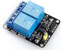
And, just when you thought it was safe to peek over the parapet..........2 Channel 5V Relay Module

Dual Relay Point Motor.jpg

Then there is this one, you'll have to work how to use this one, on your own!
Helpful hint, there is NO positive trigger!!

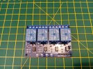
Four Relay Module.jpg
 
Last edited: