What is the best way to wire up my layout?

The mechanic

Registered
24 Nov 2016
181
15
61
South Staffordshire UK and Co. Wexford Eire
Best answers
0
Country flag
Good morning all,

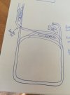
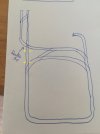
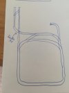
I'm looking for some help in wiring up my layout to give the best operational flexibility using analogue voltage. From the attached track plan, it can be seen that the layout consists of a basic single track loop of the garden. There is a passing loop at the top which leads through a triangular junction and a double slip, to a terminus loop. I have been wrestling with the best way to wire this as I know that I have to use diodes somewhere on the triangle to prevent short circuiting the track feeds. Any assistance in showing where to position feeds, breaks and diodes would be greatly appreciated


Thanks in advance

DaveIMG_20210322_101728.jpgIMG_20210322_112424.jpg
 
Last edited:

PhilP

G Scale, 7/8th's, Electronics
5 Jun 2013
33,562
3,521
Nottingham
Best answers
0
Country flag
We really need to know where stations and any 'industry will be?

Also how do you want to' play '?- round and round, or operational? Drop-off goods, or end to end passenger?
 

The mechanic

Registered
24 Nov 2016
181
15
61
South Staffordshire UK and Co. Wexford Eire
Best answers
0
Country flag
We really need to know where stations and any 'industry will be?

Also how do you want to' play '?- round and round, or operational? Drop-off goods, or end to end passenger?
Ideally I would like to be able to run a train round the main circuit independently of another train shuttling between the station in the top left to the station on the right. Additionally, if the train running round the the main circuit stops in the station, it can be trapped to allow a train from the station in the top left to run all the way around the loop into the bay in the top right.

It would also be good to have an operation and the ability to have two trains running round the main circuit whilst one is trapped in the platform waiting for the other one to return. This can allow some shunting to take place in the station in the top left.

Does that make sense?
 

ntpntpntp

Registered
24 Oct 2009
7,450
275
61
UK
Country
United-Kingdom
Best answers
0
Country flag
For analogue DC operation you'll need to think about isolating breaks and power feeds with switches to turn sections off and on. Single rail isolation will do for those. You have indeed created a WYE formation on the top left and this causes a polarity reversal like a reverse loop. It's not diodes that you'll need for that, it will need to be double isolated from the ovals and with some sort of double pole change over switch to select which exit track to connect to.
 

dunnyrail

DOGS, Garden Railways, Steam Trains, Jive Dancing,
Staff member
GSC Moderator
25 Oct 2009
26,168
4,992
75
St.Neots Cambridgeshire UK
Best answers
0
Country flag
Well this will work but whethet it will give you the flexibility you need will only be seen after time.
Notes.
Double means isolation to each rail.
1 Rail means Isolation to one rail and feed to that rail to power a temporary isolated train/loco, could be a push button
Feed means double feed to the track.
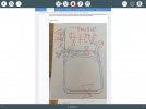
The double isolations between the slip and circle coloured green is where trains will need to stop to change polarity due to the reversing section via a DPDT Switch (double pole doible throw) y suggestion is that you make a mimic control panel with the track diagram on it and the DPDT set so the if up a train can drive from the station then stop in this section, change the switch sown and it can then run to the loop. Doing it this way will always give you a reminder of where you can drive a train to the reversing section. You should also note that any train (by that I mean electrically connected pickups) stoping in this section should not be longer than that section as this could cause shorts.

I am pretty sure that your operating requirements have been covered.
F24EC83D-5A00-45D1-9204-DAC94CE48236.png
 
Last edited:

Gizzy

A gentleman, a scholar, and a railway modeller....
26 Oct 2009
36,139
2,273
63
Cambridgeshire
www.gscalecentral.net
Best answers
0
Country flag
I reckon your simplest way is to make a break in the straight track running 'South' of the Double Slip, as shown by the yellow arrows.

You can either use a DPDT switch to change the current, or if you are happy with one way running, either 'North' or 'South', then you could use an LGB 1015T Reversal Track Set which will work automatically one way without any complex wiring....

415248_IMG_20210322_101728.jpg
 

Madman

Registered
25 Oct 2009
17,137
2,953
Pennsylvania, USA
Best answers
0
Country flag
Black to black, white to white and payday is Friday.....:rofl:.....
 

The mechanic

Registered
24 Nov 2016
181
15
61
South Staffordshire UK and Co. Wexford Eire
Best answers
0
Country flag
Well this will work but whethet it will give you the flexibility you need will only be seen after time.
Notes.
Double means isolation to each rail.
1 Rail means Isolation to one rail and feed to that rail to power a temporary isolated train/loco, could be a push button
Feed means double feed to the track.
The double isolations between the slip and circle coloured green is where trains will need to stop to change polarity due to the reversing section via a DPDT Switch (double pole doible throw) y suggestion is that you make a mimic control panel with the track diagram on it and the DPDT set so the if up a train can drive from the station then stop in this section, change the switch sown and it can then run to the loop. Doing it this way will always give you a reminder of where you can drive a train to the reversing section. You should also note that any train (by that I mean electrically connected pickups) stoping in this section should not be longer than that section as this could cause shorts.

I am pretty sure that your operating requirements have been covered.
View attachment 282718
Apologies to the delay in responding to replies - many thanks for everyone for contributing, and particular thanks to Jon for the diagram above. Such a brilliant forum from this perspective alone!

I'm afraid i've been quite busy beavering away in the garden following the replies to try to get the layout to a semi-finished state. Essentially, this is the approach that I have ended up adapting, but have also added a second DPDT switch in the location of the station as it is a natural point for trains to stop (thus allowing the switch to be used) and flexibility between running two trains on the main circuit and having one isolated on the main circuit and another shuttling between stations.

As you might be able to tell from my updated profile picture, it worked really well and allows for some interesting moves! Really happy to start running trains - just looking to bury the DPDT switches into a waterproof `building' (still undecided between signal box or just a regular hut). that I can access as and where needed and have some feed wires to tidy up, but otherwise its good to go!

Thanks again to all.