Squeezing It In!

ken lawrence

Registered
Country flag
Hi all.
I'm planning my first 45mm garden railway in North London. It's going to be a tight fit around an already full, mature garden. LGB track on a raised trackbed - and I'm thinking of using 'Filcris' components. Not the cheapest method but it looks interesting. Battery and r/c live steam.
Any experience with 'plastic timber' out there?

Best Regards
Yes I built an 0 Gauge Layout for a friend. Filcris are very helpful, will cut up Sheets to precise Radius for you. But does need plenty of Support. I used the Planking and sort of 2x1 that they do to make up U shaped Planks. Supported on Wood Posts via Metposts Postcreted into the Ground. Make sure that the bit that holds the Post at the bottom is Above Ground and the Wood Posts will not Rot.

Only problem is Expansion. The Planks expand during the day and contract at night so that we did in 0 get loads of problems with bent track. Have revised the fitting process and use Small Plastic Oblongs of HIPS 3 or 4 mm sat around every Metre or so. Allows the Track to Float during the Expansion and Contraction. DO NOT Use pins through the sleepers in the conventional way to secure the track, will only cause Tears. Would also suggest that you use Track Clamps rather than Supplied Fishplates, will keep things Aligned better. We did not have this option in 0 so resorted to sliding rail joiners that allowed the Track to move just less than the length of a Fishplate. Track Clamps should negate this.

Hope this helps, if you want more detail could post some pics of the Layout.
JonD
 
JonD,
Could you expand (sorry!) on your fixing method please?
I don't get the 'Small plastic Oblongs of HIPS 3or 4mm sat around every metre or so' bit.. - Probably me being thick!?
 
There may be some useful info in this old thread:
https://www.gscalecentral.net/threads/filcris-products-any-recommendations-or-advice.280412/

Sadly the very extensive thread on the building of Jerry (Lone) Ranger's large layout, all raised track using literally truckloads of Filcris, all seems to have been lost from the GSC archives - the links are showing as page not found. Jerry's not active on here these days but maybe he still reads occasionally, he might just see this and respond....?

Jon.
 
Our replacement display layout for the Devon & Cornwall Area Group is being used as an experiment with this, several group members having seen the product in the flesh so to speak have placed orders for further items, appears to have gone down well in these parts as a viable alternative for the construction of a garden railway, either as permanent or portable.

The new product has been somewhat revised, and the use of glue and screws has seen a better and a more secure fixing method, Mr Trainer's notes in the link below were much appreciated.

http://www.filcris.co.uk/pdf/Garden Rail Project Mr Trainer.pdf

Not used the following method, the notes supplied in the link, explain the principle:

http://www.filcris.co.uk/info/garden-railway-products/ladder-frame-kits-and-components

Edit: http://familygardentrains.com/primer/roadbed/ladder1.htm
 
Last edited by a moderator:
JonD,
Could you expand (sorry!) on your fixing method please?
I don't get the 'Small plastic Oblongs of HIPS 3or 4mm sat around every metre or so' bit.. - Probably me being thick!?
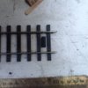
Ok so I just took a pic for you of the Oblongs (block?), a pic as they say saves a thousand words:-
image.jpeg
This is a piece of 4mm Hips just plonked into the gap between 2 Sleepers. I pre drill a hole and pin the Small Block into the exact centre when Track Laying. Allows a little movement in all directions. Of course you can restrict the movement one way or the other, but with tha amount of Expansion and the problamatic Contraction at night a little all way movement is good. If the Boards are in a full sun location they do expand by quite a bit. Probably as much as an inch over a 2.4 Metre Board. This was more of a problem with 0 Gauge than it will be with G.

I use this method on my G Line in my Fiddle Yard in the Shed, this helps with quick removal for changes, quite a few that have been done on my Fiddle Yard.

Edit - looking at the other links, on the 0 Gauge line we laid strips of Roof Felt on the Boards to represent Ballast. I think that the Grey Ballast on the Felt helps to deflect the daytime heat a little as well. Interesting that the Links do not appear to mention the Expansion/Contraction issues. Filcris were very honest to mention it to me when I was with them ordering the Product for the 0 Line.

I have not used Filcris on my Line, as a nice neighbour gave me a load of 8x2 inch Timbers. My view of these at 3ft High and covered with Roof Felt was that they would see me out! Though I have made a Small Bonsai Tray out of Filcris and it works a treat. Plus we are doing some more work with the 0 Line this Summer, extensions! Never met a line that did not need or get extensions.

Hope this all helps.
JonD
 
Last edited:
Thanks for the explanation.. So, floating track (more or less) - I like that idea..

Latest on Filcris seems to be a ladder rack with short boards laid crossways.. Small gaps can be left for drainage, and the expansion problem is much reduced..
 
I was going to try some ladder rack - the final route plan has been approved by the planning authorities; surveying will start as soon as I can borrow an engineer's level from a neighbour.
 
I was wanting to do ladder rack at ground level-ish.

In other words, as a track base, and as an edging to the garden / grass / shrub bed / whatever.

I'm not lover of raised track for the sake of it - fine where you have to level off the slope of the garden, but I'll kneel for as long as my knees will bend (I get a bit of practice most Sundays :nod::nod: )
 
Wow! This forum really was the place to ask. Thanks to everyone for the replies: here's the tricky, very small, garden the railway will have to negotiate. The realities of an urban property. Quite some trimming to do, and the track will initially follow the
perimeter, thereby breaking all best practice of accessibility (sigh). I'll post an initial track plan when I've completed it. I'd like to include a continuous run for live steam, but completing the circuit at height is a head-scratcher as a lift-out bridge(near to camera) would still make access tricky during running sessions. Any ideas?

best regards

P1020205.JPG
 
At the old place, the Wild West Sussex Railroad had a footbridge over the track to access the middle of the garden :nod::nod: :smirk::smirk: :nod::nod:
 
At the old place, the Wild West Sussex Railroad had a footbridge over the track to access the middle of the garden :nod::nod: :smirk::smirk: :nod::nod:
Cliff George's line has a couple of footbrdges over it - one, incidentally, made of Filcris..... they do get rather slippery in the wet though! Also, that's a ground-level line, so the footbridges don't have to rise more than about 12" for clearance..... with a raised line it would be much more difficult! ;)

How high are you proposing to have the raised line, Ken? If it's going to be waist-high or above, are you (and any other residents) still limber enough to duck under a bridge during running sessions, as long as said bridge was to lift out for normal garden access at non-running times?

Some makers of railclamps (Hillman?) make lift-out clamps held by sprung ballbearings, for easy removal of liftout or tilting bridges.

Jon.
 
....they do get rather slippery in the wet though!

Yes they do. The decking on my wooden bridge has been replaced with non slip decking boards like these

http://www.diy.com/departments/walk...-w120mm-l2100mm-t28mm-pack-of-5/292011_BQ.prd

They make a big difference, hopefully no one will now slip over on open days!

This is one of the jobs I did manage to get done during my recent under employment!

Some makers of railclamps (Hillman?) make lift-out clamps ...... for easy removal of liftout or tilting bridges.

Jon.

Yes and Glendale have these in stock:

http://www.glendalejunction.co.uk/RailClamps.html

Split Jaw make something similar. Note Hillmans Railclamps are no longer made.

There were some vendors at the 16mill show at Peterborough with suitable lift up bridges, sorry I can't remember their names!
 
There were some vendors at the 16mill show at Peterborough with suitable lift up bridges, sorry I can't remember their names!


I think that they are Black Cat bridges, if my memory serves me right.

In relation to Gerry's use of Filcris, he screwed his track down and the expansion of the Filcris did cause interesting 'alterations' of the track as the expansion and contraction occurred.
The 'sliding' method is definitely a solution. But I would possibly go one step further and screw a flat piece of metal to the block between the ties. This metal plate would go over the ties either side so that it kept the track down whilst allowing it to 'slide' a little whilst the Filcris did its 'heat dance'.
Also as long as any scenery was not fixed down to the Filcris bed either side of the rail bed, there would be not too much problem of movement etc. and ballst could be loose laid near to the scenery edge.


track fix with filcris.jpg

filcris and scenery.jpg
 
I think that they are Black Cat bridges, if my memory serves me right.

In relation to Gerry's use of Filcris, he screwed his track down and the expansion of the Filcris did cause interesting 'alterations' of the track as the expansion and contraction occurred.
The 'sliding' method is definitely a solution. But I would possibly go one step further and screw a flat piece of metal to the block between the ties. This metal plate would go over the ties either side so that it kept the track down whilst allowing it to 'slide' a little whilst the Filcris did its 'heat dance'.
Also as long as any scenery was not fixed down to the Filcris bed either side of the rail bed, there would be not too much problem of movement etc. and ballst could be loose laid near to the scenery edge.


View attachment 207248

View attachment 207247

That is exactly what I thought would be ideal when I first read this thread! Additionally (if needed), the ends of the sleepers could be shouldered to prevent lateral movement.
 
View attachment 207239[/QUOTE]
That is exactly what I thought would be ideal when I first read this thread! Additionally (if needed), the ends of the sleepers could be shouldered to prevent lateral movement.

Preventing movement is just what you DO NOT WANT with Filcris, you do need to allow for this as I said in Post 7.

Ken, if you are thinking of a High Level Line a Bridge that lifts at one end will work fine. I used one of the Trainline Bridges on my friends 0 Gauge Line. Hinged at one end with slightly lifted Hinges that end so that the Rails do not catch. At both ends you can use loosely fitting Fishplates for Track Alignment. Hillman used to do Bridge Clamps, but these may be Tricky to find now. Then via a Micro Switch that the Bridge Activates when down, make Isolation Sections either side of the Bridge to stop Accidents. System works perfctly on his 0 Gauge Line, though you do need something to Hold the Bridge when 'Up'. We used a vertical piece of Wood.

Have left you a message in Conversations.
JonD
 
Back
Top Bottom