Reverse loop setting up, carn't get it to work.

Nodrog1826

Professional Idiot
Country flag
I am well and truly stumped on this one. I am trying to install a crossover in the style of a diagonal on a oval, but in a compressed space., using a Massoth loop module.

No matter how I try and set it up I carn't get it to work, there is either a dead short in the main loop or on the actual crossover at some point, so I am open to suggestions.

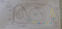
The current state of play is as follows...

20250803_131721_02[1].jpg
...those wires are for the pointmotors and the switch decoder, so ignore them.

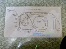
20250803_132613[1].jpg
...the module as currently wired L to R matches the clockface positions of the end wires...

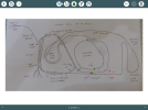
20250803_131744_01[1].jpg...is the crossover too short and I need to revise the track to extend the loop towards the bridge? That will be a civils job, but not this year.

Finally a link to the Massoth instructions...


Now as my strap line says "professional Idiot" but someone out there must have done something similar.
 
I think that possibly you may need to do the unit on one of the loops for the full length of your longest train. Would really need to see a rough sketch of the bit of line involved and the way it is wired in now. For DCC I tend to talk in er and outer line rather than plus or negative, but those will work for me as well.
 
I agree with JD.

Are you just changing the polarity on the short section of track between the points Gordon?

The track length needs to be at least as long as your longest loco, and Kroks are big beasties!

Ideally, the reverse section needs to be as long as your longest train. I had to revise my reversing loops to fit in a 7 car TEE train that takes power from each end of the train....
 
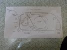
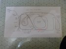
OK track diagram...

P1030903.JPG

...it's old, recycled from another part of the forum, so my idea was to make two crossovers either end of where it says "50 ft Straight", the first one is where the "T" is in order to divert a train from the station "East Throat" via the bridge onto the straight then onto the spiral, thus turning the train around so it comes back up the "40 ft straight" and then via "Seaweed Cutting" back to the station., via the "East Throat".
As for the polarity thing, although the parallel tracks where they run together are basically opposite sides of an oval.
 
Last edited:
OK track diagram...

View attachment 345866

...it's old, recycled from another part of the forum, so my idea was to make two crossovers either end of where it says "50 ft Straight", the first one is where the "T" is in order to divert a train from the station "East Throat" via the bridge onto the straight then onto the spiral, thus turning the train around so it comes back up the "40 ft straight" and then via "Seaweed Cutting" back to the station., via the "East Throat".
As for the polarity thing, although the parallel tracks where they run together are basically opposite sides of an oval.
Looking at the track diagram, putting a crossover where you have has connected lines of opposite polarity. If anything with metal wheels goes over the join you have a short circuit.
 
You can't simply put a crossover there and expect to work with only a very short section of track isolated from the main power feed. Basically you have formed a triangle/wye track configuration by introducing the new crossover. Your best bet is, probably, to fit the Massoth reversing unit along the outside track on the 50 foot straight. I'll do a diagram for you a bit later today.
 
Ok, I think I I've understood what you are describing, first and most obvious is a longer feed as long as your longest (lit) train,

1754261010781.jpeg

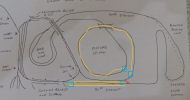
For the other route, you could (with 2 modules) apply one along 50ft st and the other could go just about anywhere in the loop, I've drawn it where you already have the track in bits.


1754260961878.png
 
Based on the junction that you have created, you could add a second section to correct the electrical issue like this.

1754265519937.png


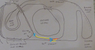
You could also add in second reversing section like this though you would need make sure that you wire both sides coming out of the original track section, you'll also need to look into multiple sections at once with this design. you may need to disable short protection on the modules or it may be possible to power the module separately as you would do with analogue operation.

1754267999469.png

You may also need to push some of the zones around so you don't have trains straddling 2 zones, and with that in mind you may be best with the 1st and the seaweed part of the 4th.
 
Last edited:
Ok then food for thought.
I should have looked at what the other have done, certainly there are many options to confuse!

My thoughts were along the lines of Craig post i where he utilizes the Ossurb Spiral, you could use all of that so that your wires and isolations were all pretty close to each other though on very different lines. Note I have annotated lines by +/- to help understand how the polarity changes round the loops, yes I know polarity not appropriate for AC but it helps to differentiate the sides.

IMG_8670.png

Not sure what plan you have for the unit, but it should be kept in a dry environment say a building. Though indoors with long wires would be better, here having the wires marked in some way like I suggested earlier would be a great help.
 
dunnyrail dunnyrail The wires are marked as per their position in the module +/- in, +/- out, Sens in (S)1,2,3,&4. The junction box containing the module is an water ingress resistant IP66. The actual wires dissapear through a hole in the slab, to the junction box via a "drip loop", so it is out of the weather, but for good measure the cably entry gland is also sealed and there was silica gel packet inside and I had taped around the lid join as well, more of a belt n braces job. The point switch module is done in the same way. The final job which wasn't done was to seal the hole in the slab to prevent water ingress to the underside.
It now looks as if it will all be coming out and plain track reinstated whilst I figure out a redesign, which I will post later, Ph IV of the layout I am now calling it.
 
So, this is what I am thinking about doing next. Will involve a bit of civils work, so not this year.

20250804_205342[1].jpg

Sort of before and after, with a smaller sketch of what it is in principal. I will need to move the tracks apart to get a third one in with clearance, and installl the other one leading to the spiral bridge. Both will need the trackbed to have a width extension.
 
My +/- was in part wrong in post 12, sorry about that. Best to redo your diagram showing both lines on your complete layout, 1 black and the other red. This will highlight where problems can occur with the opposing powered line joining the other.

I am pretty sure your revision should work with the new long bits having a reverse loop module each. Providing your longest train will fit in the new track sections.
 
So, this is what I am thinking about doing next. Will involve a bit of civils work, so not this year.

View attachment 345912

Sort of before and after, with a smaller sketch of what it is in principal. I will need to move the tracks apart to get a third one in with clearance, and installl the other one leading to the spiral bridge. Both will need the trackbed to have a width extension.

looks good and with this design, you'll also be getting the option of storing trains in those loops.
 
Leave your original track plan alone. You simply need to do the isolations just after the frogs on that junction on the straight legs. Your photo doesn't match align with the track plan.
Edit. Now I see what you have done, added a new crossover along the 50 foot straight, is that what's in the photo? For any reverse loop, there will always be two points of electrical conflict, usually at the back of the frogs where the loop starts/finishes. Realistically there needs to be a length of 'reversed polarity' at least the length of the longest train. I did all my reverse loops with simple DPDT switches. O.K., that requires a train stop to do the reversing, but, you have to change the points in any case, so a stop is prototypical.
 
Last edited:
I have found somethine else, which is more like what I wanted to do, whilst it is not a spot on for my track plan, it's close enough.


Reply 8 is what I was planning, but reply 11 appears to be a soluition, if I can figure out how to set it up, will need an extra pair of points and probably an extra module.
For starters if I flip the points around I can acheive 4-5 section of the diagram, if it works then when I get the parts install crossover 3, which will bring it into line with my initial idea that a train from either direction can be reversed. The important thing is that there will be no civils involved.
 
Back
Top Bottom