JimmyB
Now retired - trains and fishing
This is how I replaced the terminal block on a Piko Point Motor, I am NOT a professional electronics person, so any (constructive) criticism is welcome. I used the terminal block as supplied by RC Trains for use on LGB point motors, it seems to fit perfectly.
Remove the SIX screws securing the top.

This is what the inside looks like, similar to an LGB point motor, but this has a rubber seal.

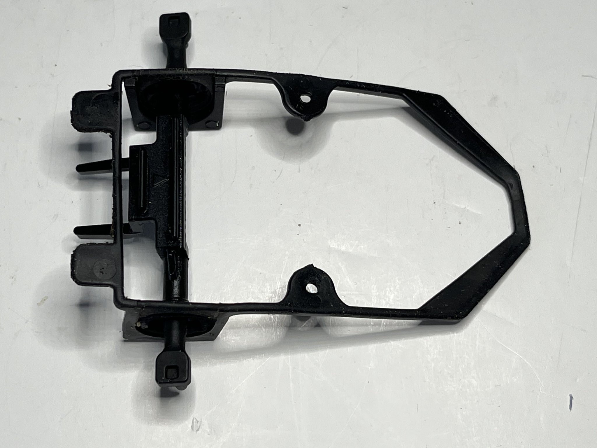
The driven rack is fitted into the seal so these are removed as a single item, note there are two (one each side) retaining spacers.

The motor unit is now removed, the two side plates will almost certainly fall off, also note that the drive pinion has a small "stop" that is on the underside.

On assembly the side plates slot into the drive with the long ends at the pinion end. You can just see the "stop" on the pinion, this limits the movement "back and forth", position is vital on assembly.

Carefully desolder the winding connections, I did a resistance test (2.3 ohm), this is to ensure that reconnected a similar value is achieved before re-assembly.

TBC!!
Remove the SIX screws securing the top.

This is what the inside looks like, similar to an LGB point motor, but this has a rubber seal.

The driven rack is fitted into the seal so these are removed as a single item, note there are two (one each side) retaining spacers.

The motor unit is now removed, the two side plates will almost certainly fall off, also note that the drive pinion has a small "stop" that is on the underside.

On assembly the side plates slot into the drive with the long ends at the pinion end. You can just see the "stop" on the pinion, this limits the movement "back and forth", position is vital on assembly.

Carefully desolder the winding connections, I did a resistance test (2.3 ohm), this is to ensure that reconnected a similar value is achieved before re-assembly.

TBC!!


 ). Points (puns
 ") ) to watch out for:
) to watch out for:
