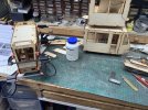
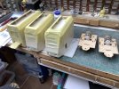
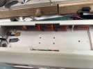
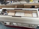
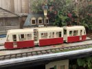
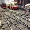
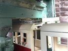
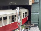
I have been beavering away at this for some time now and will be glad to get it off the bench. I have been a little reluctant to post on this but as ‘3 Minutes if Fame‘ asked me about how I was getting on with it I though I better write some words.
I have had a few problems with missing bits but these were sorted very quickly once you can get through to NP, best try in the evening as no contact managed during the day. Emails to the webb site not responded to either. Instructions leave a lot to be desired, better a few selected pictures rather than lots of words that do not cover the eventualities. Plus I believe that the instructions have been changed somewhat and with a set of duplicate pictures one with notes and seating diagram the other no seating diagram etc,all of that is a pity as this has the makings of a great model. For the kit to include all of the wiring parts, LED’s, batteries, charger, switches, motor etc it is a good value kit. Let down only by the Instructions. These were not numbered so a beginner could easily get lost, I numbered them all immediately I got them out of the box hoping that they were all in the correct order, they were (I think).
I have regarded the kit more like a set of parts to make up as I feel, this has given me the ability to do changes and not make it up as a 5 car that I bought but as 3 car somewhat on the lines of the Nordhausen Combino’s, but the finished item will be in HSB livery as if they had a few sets as well for services out to the Selktalbahn.
Where to start on these notes is a bit tricky so I will start sort of at the begining, in those immortal Julie Andrews words ‘that‘s a very good place to start’.
The kit comes with an awful lot of parts, all neatly packed in almost all labelled bags for what they are. The laser cutting is nice and neat with parts fit being mostly near perfect, but be prepared for a small amount of sanding on mostly tabs to get things in place.
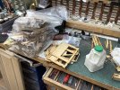
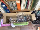
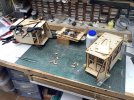
I started inevitably with the light fittings that go into the front of the Tram and to be honest this did not make much sence till further down the line. But I persevered with it as it was on my Page 1. I did however not do the LED’s fit as I want to get things painted before this for obvious reasons. This has applied to all lighting and wiring.
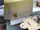
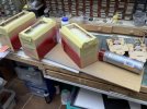
Next up was to construct the front part of the Tram and this was attended to and left to dry making sure that all was square as the instructions suggested . At this stage I think some suggestions to part paint the inside would have been helpful, ensuring that clean wood was left where things would be joined. The inside is still not fully painted even after my spraying so that is something that will become a problem later. I am not at all sure that NP has even thought through painting as all of their pictures are of an unpainted one, and as I have never seen any other reviews thus I am a little confounded by this.
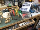
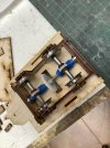
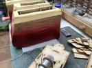
So onwards and forwards with the working power bogies, these left me a bit flummoxed as with the side frames as when constructed and the cross fills below added the lay shaft was completely at a woblle end to end so additional off cuts were fitted in to get the gears so that there was little wobble. Then the gears are somewhat poorly cast so a fair bit of cleaning up is required to get them to run feely. It was around this stage I seriously thought about buying a couple of Swift Sixteen Flexible length chassis to replace these, but I persevered. Once in place I resorted to Tooth Paste to act as a grinder to get a free running chassis, just remember to clean it all out. The picture of the bule gear clearly shows the ridges, though the instructions do tell of this and how to resolve it.
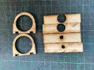
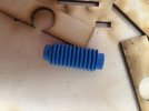
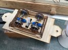
The axle ends are fitted with roller bearings as are the layshafts, very good and this shows the promise of the NP product. The axle gear is held in place by a couple of laser cut washers which so with plenty of 806 and some UV glue held them and the kayshaft gers in place very well. However when fitted the axle gears and layshaft gears were far too tight a mesh to even turn the axles With the end plates in place one way up, nowhere near in mesh the other way up. Thus I had to open up the holes and move the bearings down. A better bet adopted on the second one was to fit the end plates the wrong way down with some slight sanding to get the mesh perfect. Both chassis run well now and much to my skeptical thoughts the motor gears meshed with the layshaft to perfection! Oh yes the motor gear comes with some heatshrink and a small plastic bearing to fit to the motor shaft. I was also very skeptical about this but with some 806 and more UV glue it all seams pretty solid.
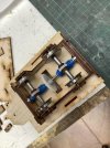
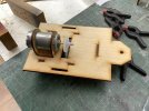
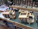
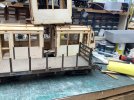
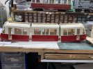
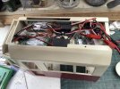
Next up come the body build and fitting the chassis. The instructions give this as an all glue together assembly, I did not warm to that idea as I like to be able to remove the motor as necessary, so the bogie (for want of a better term) was fitted after all the other surrounding driver end, then drilled for 4 of 8ba nut and bolt fitting. This has worked very well but gives issue later in the build as it will not be possible to fit the internal seats and hand rails as the bogie now needs to be twisted to remove from the corridoor end. Current thoughts are for sub assembly for seats and handrails to go in and out for each side. But that motor will take some disguising as it sits very high in the body. time will tell but a few passengers and some standing may just do the job.
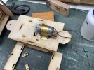
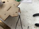
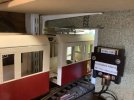
As you can see the bogie has wires coming from the motor for testing and ultimate wiring in. I made the effort to oair them and mark one side so that they will both run the same way when wired up. A small piece of Red heat shrink acts as a marker but I should have made the wires longer as they only just reach the roof top when in place. I will runthem up at one end and may need to do a plug at the motor end for this, more grey matter bites the bullet.
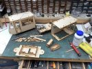
I have had a few problems with missing bits but these were sorted very quickly once you can get through to NP, best try in the evening as no contact managed during the day. Emails to the webb site not responded to either. Instructions leave a lot to be desired, better a few selected pictures rather than lots of words that do not cover the eventualities. Plus I believe that the instructions have been changed somewhat and with a set of duplicate pictures one with notes and seating diagram the other no seating diagram etc,all of that is a pity as this has the makings of a great model. For the kit to include all of the wiring parts, LED’s, batteries, charger, switches, motor etc it is a good value kit. Let down only by the Instructions. These were not numbered so a beginner could easily get lost, I numbered them all immediately I got them out of the box hoping that they were all in the correct order, they were (I think).
I have regarded the kit more like a set of parts to make up as I feel, this has given me the ability to do changes and not make it up as a 5 car that I bought but as 3 car somewhat on the lines of the Nordhausen Combino’s, but the finished item will be in HSB livery as if they had a few sets as well for services out to the Selktalbahn.
Where to start on these notes is a bit tricky so I will start sort of at the begining, in those immortal Julie Andrews words ‘that‘s a very good place to start’.
The kit comes with an awful lot of parts, all neatly packed in almost all labelled bags for what they are. The laser cutting is nice and neat with parts fit being mostly near perfect, but be prepared for a small amount of sanding on mostly tabs to get things in place.


I started inevitably with the light fittings that go into the front of the Tram and to be honest this did not make much sence till further down the line. But I persevered with it as it was on my Page 1. I did however not do the LED’s fit as I want to get things painted before this for obvious reasons. This has applied to all lighting and wiring.
Next up was to construct the front part of the Tram and this was attended to and left to dry making sure that all was square as the instructions suggested . At this stage I think some suggestions to part paint the inside would have been helpful, ensuring that clean wood was left where things would be joined. The inside is still not fully painted even after my spraying so that is something that will become a problem later. I am not at all sure that NP has even thought through painting as all of their pictures are of an unpainted one, and as I have never seen any other reviews thus I am a little confounded by this.

So onwards and forwards with the working power bogies, these left me a bit flummoxed as with the side frames as when constructed and the cross fills below added the lay shaft was completely at a woblle end to end so additional off cuts were fitted in to get the gears so that there was little wobble. Then the gears are somewhat poorly cast so a fair bit of cleaning up is required to get them to run feely. It was around this stage I seriously thought about buying a couple of Swift Sixteen Flexible length chassis to replace these, but I persevered. Once in place I resorted to Tooth Paste to act as a grinder to get a free running chassis, just remember to clean it all out. The picture of the bule gear clearly shows the ridges, though the instructions do tell of this and how to resolve it.


The axle ends are fitted with roller bearings as are the layshafts, very good and this shows the promise of the NP product. The axle gear is held in place by a couple of laser cut washers which so with plenty of 806 and some UV glue held them and the kayshaft gers in place very well. However when fitted the axle gears and layshaft gears were far too tight a mesh to even turn the axles With the end plates in place one way up, nowhere near in mesh the other way up. Thus I had to open up the holes and move the bearings down. A better bet adopted on the second one was to fit the end plates the wrong way down with some slight sanding to get the mesh perfect. Both chassis run well now and much to my skeptical thoughts the motor gears meshed with the layshaft to perfection! Oh yes the motor gear comes with some heatshrink and a small plastic bearing to fit to the motor shaft. I was also very skeptical about this but with some 806 and more UV glue it all seams pretty solid.


Next up come the body build and fitting the chassis. The instructions give this as an all glue together assembly, I did not warm to that idea as I like to be able to remove the motor as necessary, so the bogie (for want of a better term) was fitted after all the other surrounding driver end, then drilled for 4 of 8ba nut and bolt fitting. This has worked very well but gives issue later in the build as it will not be possible to fit the internal seats and hand rails as the bogie now needs to be twisted to remove from the corridoor end. Current thoughts are for sub assembly for seats and handrails to go in and out for each side. But that motor will take some disguising as it sits very high in the body. time will tell but a few passengers and some standing may just do the job.
As you can see the bogie has wires coming from the motor for testing and ultimate wiring in. I made the effort to oair them and mark one side so that they will both run the same way when wired up. A small piece of Red heat shrink acts as a marker but I should have made the wires longer as they only just reach the roof top when in place. I will runthem up at one end and may need to do a plug at the motor end for this, more grey matter bites the bullet.


