curtis
Registered
Over the last day or so, I've been fitting a DCC servo-controlled uncoupler to an LGB 2070 U-Class. I thought I'd share the process and my learnings should it help others considering something similar.
You can see a video of this in action onInstagram YouTube:
I should start of my clarifying this is not a "plug and play" solution. In order to get the uncoupler installed, it required some changes to the uncoupler, trimming the plastic of the arm holding the trailing wheels and drilling a hole to run the wires from the servo to the regulator & decoder. Given I intend to hold my collection until I can no longer play trains I didn't have too much concern about resale value and enjoy a challenge and learning something new.
This is my second loco to add a DCC controlled loco uncoupler..The first attempt was an LGB 2015 which also required internal "modifications" (read: dremmel and drilling the inside of the tender) to setup but is working well (@65 1057 can attest he saw it live during our running session). For me, this flexibility made things a lot more fun so wanted to slowly expand the functionality to the rest of the stock.
Parts
Placement
On the LGB 2015 (my previous attempt), the hook/loop coupler is attached to the body of the tender. This means the servo can be located in the tender and the fishing wire fed down to the coupler. However, on the LGB 2070, the coupler is attached to a pivoting trailing wheel via an arm. The servo is configured for very specific range of motion so mounting the servo in the body itself was a no go. Unless positioned perfectly at the point of the pivot (which was not possible) it would have meant a variability in the length of the wire between the servo and the mechanism. The only choice was to mount the servo itself to the arm of the trailing wheels.

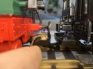
First, I had to make this wouldn't interrupt the functioning of the loco. I took the servo and some blue tac and mounted the servo to the top of the arm just below the body of the loco (their wasn't room below). I then carefully ran the loco through various s-curves (R1, naturally) and a mess of points to find all ran well. The initial prototype, at least, worked well.
Modifying the Heyns Uncoupler
The Heyn's uncoupler functions to uncoupler wagons connected both with a single and double hook. It works by pressing a plate down into to the hook. This has the double effect of pressing down the hook from the connected wagon and the hook on the loco itself. Once depressed, the loco can simply move forward...
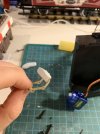
In theory at least. I found with both locos the range of motion isn't quite enough for the plate to push the hook of the wagon far enough down so I've had to pad the plate with additional thickness (example below from the unfinished Spreewald)

For the Tenderlok, I use PVC sheeting but for this I used some milliput. For those of you that haven't used it, milliput is a modelling material that has the texture of bluetac to work with and then sets solid in several hours (so solid, you can drill into it). I used this to create the additional padding and tested it with a couple of wagons.


Attaching the Servo
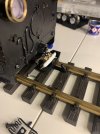
This was one of the more challenging parts of this endeavour. I tried using milliput to create a structure so I could swap our servos if (when..) I break them. That didn't quite work. I considered just supergluing the servo to the arm (definitely the simplest) but again, when I break them means I'd have to replace the entire trailing wheel arm which seems wasteful. In the end, I decided to superglue a yellow track insulator in the right position so I could screw the servo to it. This seems a reasonable compromise for maintainability. It was also the right decision because when initially programming the decoder I misconfigured it servo and damaged the gears on the first one )
Wiring and configuring the servo
This was the easiest part of the install. I already had a Dec+ running to the back of the loco for the rear and interior lights. The Dec- was running to the cab too because I've used the cab switch (the one in analogue that disables lights/motor) as a switch for the DIY Power Buffer. I simply extended a wire from the Dec- to the voltage regulator. The only additional wire I had to run was for the function output which was easy.
I drilled a hole in an accessible place to run the wires from the servo up into the cab and wired in the servo to the voltage regulatory. I then used computer software to configure the decoder and a basic range of motion for the decoder. I tested this without any attachment to the uncoupler to avoid damaging anything.
Once I had a range of motion that looked reasonable, I set the servo to the uncoupled position and attached the servo to the uncoupling mechanism wire the attached wire. I then disabled the uncoupling function to restore the servo and the uncoupling mechanism to the "normal" position.
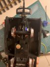
You can see the configuration in the first image.
What's next?
I want to do a few sessions with the attached prototype before I consider it a success but from a 15minute play this evening I'm happy do far. Once I'm confident it works, I'll clear up the modified arm and paint in back (not that it is noticeable from the outside) but makes me feel better. I also need to paint the white milliput clay either in the gold/brass colour or black.
Let me know your thoughts or if anything was unclear!
Curtis
You can see a video of this in action on
I should start of my clarifying this is not a "plug and play" solution. In order to get the uncoupler installed, it required some changes to the uncoupler, trimming the plastic of the arm holding the trailing wheels and drilling a hole to run the wires from the servo to the regulator & decoder. Given I intend to hold my collection until I can no longer play trains I didn't have too much concern about resale value and enjoy a challenge and learning something new.
This is my second loco to add a DCC controlled loco uncoupler..The first attempt was an LGB 2015 which also required internal "modifications" (read: dremmel and drilling the inside of the tender) to setup but is working well (@65 1057 can attest he saw it live during our running session). For me, this flexibility made things a lot more fun so wanted to slowly expand the functionality to the rest of the stock.
Parts
- x1 Heyns Uncoupling Arm (purchased as a set from Modell-land.de including the wire)
- x1 SG90 Servo (bought as a set from Amazon)
- x1 Milliput (although I only used a fraction of it)
- x1 6v Voltage Regulator (from MD-Electronics)
Placement
On the LGB 2015 (my previous attempt), the hook/loop coupler is attached to the body of the tender. This means the servo can be located in the tender and the fishing wire fed down to the coupler. However, on the LGB 2070, the coupler is attached to a pivoting trailing wheel via an arm. The servo is configured for very specific range of motion so mounting the servo in the body itself was a no go. Unless positioned perfectly at the point of the pivot (which was not possible) it would have meant a variability in the length of the wire between the servo and the mechanism. The only choice was to mount the servo itself to the arm of the trailing wheels.

First, I had to make this wouldn't interrupt the functioning of the loco. I took the servo and some blue tac and mounted the servo to the top of the arm just below the body of the loco (their wasn't room below). I then carefully ran the loco through various s-curves (R1, naturally) and a mess of points to find all ran well. The initial prototype, at least, worked well.
Modifying the Heyns Uncoupler
The Heyn's uncoupler functions to uncoupler wagons connected both with a single and double hook. It works by pressing a plate down into to the hook. This has the double effect of pressing down the hook from the connected wagon and the hook on the loco itself. Once depressed, the loco can simply move forward...
In theory at least. I found with both locos the range of motion isn't quite enough for the plate to push the hook of the wagon far enough down so I've had to pad the plate with additional thickness (example below from the unfinished Spreewald)

For the Tenderlok, I use PVC sheeting but for this I used some milliput. For those of you that haven't used it, milliput is a modelling material that has the texture of bluetac to work with and then sets solid in several hours (so solid, you can drill into it). I used this to create the additional padding and tested it with a couple of wagons.


Attaching the Servo
This was one of the more challenging parts of this endeavour. I tried using milliput to create a structure so I could swap our servos if (when..) I break them. That didn't quite work. I considered just supergluing the servo to the arm (definitely the simplest) but again, when I break them means I'd have to replace the entire trailing wheel arm which seems wasteful. In the end, I decided to superglue a yellow track insulator in the right position so I could screw the servo to it. This seems a reasonable compromise for maintainability. It was also the right decision because when initially programming the decoder I misconfigured it servo and damaged the gears on the first one )
Wiring and configuring the servo
This was the easiest part of the install. I already had a Dec+ running to the back of the loco for the rear and interior lights. The Dec- was running to the cab too because I've used the cab switch (the one in analogue that disables lights/motor) as a switch for the DIY Power Buffer. I simply extended a wire from the Dec- to the voltage regulator. The only additional wire I had to run was for the function output which was easy.
I drilled a hole in an accessible place to run the wires from the servo up into the cab and wired in the servo to the voltage regulatory. I then used computer software to configure the decoder and a basic range of motion for the decoder. I tested this without any attachment to the uncoupler to avoid damaging anything.
Once I had a range of motion that looked reasonable, I set the servo to the uncoupled position and attached the servo to the uncoupling mechanism wire the attached wire. I then disabled the uncoupling function to restore the servo and the uncoupling mechanism to the "normal" position.
You can see the configuration in the first image.
What's next?
I want to do a few sessions with the attached prototype before I consider it a success but from a 15minute play this evening I'm happy do far. Once I'm confident it works, I'll clear up the modified arm and paint in back (not that it is noticeable from the outside) but makes me feel better. I also need to paint the white milliput clay either in the gold/brass colour or black.
Let me know your thoughts or if anything was unclear!
Curtis
Last edited:
