Not being aware of this correction in the manual was the cause of me destroying two Massoth 8122302 lighting boards as described elsewhere on this site. Pictured below are the offending and corrected pages of the manual:
The original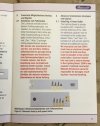 . The corrected
 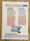 . Note the reversed solder pad labelling in Figure 2. The actual board is not labelled so this is the only guidance.
The next few pics illustrate how I installed the lighting boards (and buffer capacitor) in a LGB long wheelbase 2 axle passenger wagon.
First up is a shot of the buffer capacitor soldered to the correct pads! Please excuse the ugly solder job - unlike some prior workmates, I never attended soldering school.
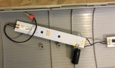 Next are the Digital and companion analog boards screwed to the roof.
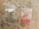
 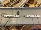 The digital board A2 function output is used to power the analog board. You might recognize the orange bodied pins as LGB no. 50131 wire terminals. The "sockets" (covered by the green shrink tube) are single pin crimp-on connectors commonly used by LGB and others. I happened to get these from All About LGB.
The capacitor I used was a 35V 560µF electrolytic. I bought some 2200µF caps too just in case the 560s wouldn't store enough juice. However, the 560µF caps function OK for my situation. The 2200µF caps were so big physically they would have needed mounting underneath the chassis with wires going up to the board. The 560s are not visible, being hidden in the crown of the roof. You can't see the capacitor unless you get in a position to actually look up into the wagon.
The next few of shots are of the chassis bottom and wagon interior showing how I got power to the lighting boards.
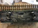
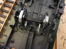
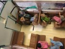
A few comments. The wheels are LGB no. 67403 Ball Bearing Wheel Sets. The single axle trucks have an opening molded in that allows for the passage of wires as does the chassis. If you remove the chassis from the body you will see a drilling "target" molded in the bottom of the body that matches up with the wire hole in the chassis. In the first of the three pics above you can see how I routed the wires from one pair of axle connectors to the axle connectors on the second axle. Another pair of wires go from the second axle's connectors into the wagon interior.
I used 3M no. 3798LM low temperature hot melt glue to secure the wires. It was also used to glue the passengers in place. I've mentioned this low temp hot melt glue in this site before and it is worth mentioning again. This stuff works great but you need an adjustable temperature glue gun to use it properly. The glue sticks themselves are standard size. 3M makes a dedicated glue gun but it is a very pricey industrial quality piece of equipment. I really like the glue because its melting temperature is low enough to not affect plastics and it will come off cleanly if you need to remove it. It's the same glue you will see used to attach credit cards and such to paper.
Edit added: With the buffer cap installed I'm going to see if I can get away with power from a single wheel set. Might save me some coin when I put lights in the Furka Bergstrecke coaches I've got. One ball bearing wheel set costs about the same as one of the digital lighting boards I blew up!
Another edit added: Make sure you program the lighting boards first unless you provide some way to easily disconnect the buffer capacitor!
The original
 . The corrected
  . Note the reversed solder pad labelling in Figure 2. The actual board is not labelled so this is the only guidance.
The next few pics illustrate how I installed the lighting boards (and buffer capacitor) in a LGB long wheelbase 2 axle passenger wagon.
First up is a shot of the buffer capacitor soldered to the correct pads! Please excuse the ugly solder job - unlike some prior workmates, I never attended soldering school.
 Next are the Digital and companion analog boards screwed to the roof.
  The digital board A2 function output is used to power the analog board. You might recognize the orange bodied pins as LGB no. 50131 wire terminals. The "sockets" (covered by the green shrink tube) are single pin crimp-on connectors commonly used by LGB and others. I happened to get these from All About LGB.
The capacitor I used was a 35V 560µF electrolytic. I bought some 2200µF caps too just in case the 560s wouldn't store enough juice. However, the 560µF caps function OK for my situation. The 2200µF caps were so big physically they would have needed mounting underneath the chassis with wires going up to the board. The 560s are not visible, being hidden in the crown of the roof. You can't see the capacitor unless you get in a position to actually look up into the wagon.
The next few of shots are of the chassis bottom and wagon interior showing how I got power to the lighting boards.


A few comments. The wheels are LGB no. 67403 Ball Bearing Wheel Sets. The single axle trucks have an opening molded in that allows for the passage of wires as does the chassis. If you remove the chassis from the body you will see a drilling "target" molded in the bottom of the body that matches up with the wire hole in the chassis. In the first of the three pics above you can see how I routed the wires from one pair of axle connectors to the axle connectors on the second axle. Another pair of wires go from the second axle's connectors into the wagon interior.
I used 3M no. 3798LM low temperature hot melt glue to secure the wires. It was also used to glue the passengers in place. I've mentioned this low temp hot melt glue in this site before and it is worth mentioning again. This stuff works great but you need an adjustable temperature glue gun to use it properly. The glue sticks themselves are standard size. 3M makes a dedicated glue gun but it is a very pricey industrial quality piece of equipment. I really like the glue because its melting temperature is low enough to not affect plastics and it will come off cleanly if you need to remove it. It's the same glue you will see used to attach credit cards and such to paper.
Edit added: With the buffer cap installed I'm going to see if I can get away with power from a single wheel set. Might save me some coin when I put lights in the Furka Bergstrecke coaches I've got. One ball bearing wheel set costs about the same as one of the digital lighting boards I blew up!
Another edit added: Make sure you program the lighting boards first unless you provide some way to easily disconnect the buffer capacitor!
Last edited:
