Massoth decoder brake on DC

idlemarvel

Neither idle nor a marvel
13 Jul 2015
3,136
801
Ascot
Country
Mars
Best answers
0
Country flag
I believe Massoth motor decoders support brake on DC. I can't find any Massoth documentation on this but I understand the way it works is that you have a section of analog DC powered track and when the DCC configured loco hits the DC section it slows down to a stop, until DCC power is restored. I understand you have to configure the decoder not to support DC in CV 29. Is that all there is to it? Has anyone on here tried it? Any hints and tips gratefully received before I give it a go.
 

Neil Robinson

Registered
24 Oct 2009
9,699
579
N W Leicestershire
Best answers
0
Country flag
I suspect this may not help and may increase confusion despite my posting hoping to introduce a little clarity.
I'm fairly sure that many decoder manufactures have brake on DC.
Many, if not all, LGB/Massoth decoders have a brake, pause, reverse and accelerate function on DC that may or may not be a similar thing. I use it on an automatic shuttle service with a dc track supply that reverses polarity via reed relays at a suitable distance from each end of a single track branch line.
 

phils2um

Phil S
11 Sep 2015
1,522
423
Ann Arbor, Michigan
Country
United-States
Best answers
0
Country flag
HI Dave - the below is directly from the Massoth XLS Manual dated 08/08. I quote:

"Automatic Braking (since V1.3)
There are two methods to stop a train in front of a stop signal automatically. The first method uses DCC brake
signals produced by a booster with a breaking module (Broadcast), the second method utilizes a DC signal
(Brake-On-DC). For both methods a track portion in front of the signal must be totally isolated and powered by
the respective signal. For Brake-On-DC the option for analog operation must be blocked (CV 29, Bit2). Please
check your DCC system manual for further information."

Re-reading your original post I suspect you are aware of this! Looks to me that disabling analog operation is all you need to do to get Brake-On-DC. (And the isolated track sections too of course.) I do wonder if it stops dead or the momentum settings ease the halt. Also, if a Power Cap is necessary , which I suspect, for momentum to work. Let us know how you get on.
 
Last edited:

idlemarvel

Neither idle nor a marvel
13 Jul 2015
3,136
801
Ascot
Country
Mars
Best answers
0
Country flag
Thanks Phil. Yes I had seen that but it seems that is all they have to say on the subject. I wonder about power caps. I assume the decoder uses the analog power to drive the motor until it comes to a halt, and a power cap may interfere with that. Also I don't know whether the polarity of the DC matters. Other non-G-scale non-Massoth sources warn about mixing the DCC and DC signals, so I have a concern about skates bridging the gap if you just use normal insulated rail joiners to separate the DCC and DC sections.
 

idlemarvel

Neither idle nor a marvel
13 Jul 2015
3,136
801
Ascot
Country
Mars
Best answers
0
Country flag
Thinking more about "not mixing the signals" at first I thought if you allowed for the size of skates that would be enough. But I am wondering how long a "dead zone" needs to be. In a loco all the pick-up points converge onto the decoder track input connectors. Unless the dead zone is longer than the distance between the first and last pick-ups, at some stage you will be mixing DCC and DC, effectively applying a DC voltage across a live DCC track. I can't thank that's good for the command station even if the decoder can somehow handle it. And if the dead zone is that long, at slow speeds the loco is going to stall. Maybe I have this wrong and it will all just work. Still hoping someone has done it before and can chip in?
 

idlemarvel

Neither idle nor a marvel
13 Jul 2015
3,136
801
Ascot
Country
Mars
Best answers
0
Country flag
I'm beginning to think this is a non-starter (hah!) or at least is far more complicated than the title suggests.

The issue of the "dead zone" seems to be a bit of a show-stopper. In the early days of DCC, Lenz made a module called LT100 Separation Module which handles just this issue. When people were experimenting with DCC, you could use it to bridge between DCC and DC part of your layout. It handles the transition between the two by very quickly shutting off the analog DC signal if DCC is detected in the transition zone, before any damage can be done. In a similar way it handles a DC braking section in a mainly DCC layout.

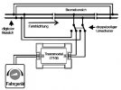
So far so good but a) it costs (or rather did cost) £35 per section and b) it has been out of production for years. I have found an old manual and this picture shows how it would have worked in braking section mode.
lt100.JPG
(rough translations: Bremsbereich braking section, Fahrtrichtung direction of travel, doppelpoliger Umschalter double-pole switch, Fahrgenerat analog controller, digitaler Bereich DCC section)

It is clear that this is not as simple as adding a section of DC powered track.

I have found other articles suggesting you could build your own circuit with a fast response Shottky diode and snubber to convert the DCC signal into a pulsed DC which would not cause a short, but it seems a bit risky when if it doesn't work it's goodnight Vienna to your command station.

There are other DCC solutions for braking, but tend to involve proprietary modules that issue a DCC "set speed to 0" command to locos in that section, and are not particularly cheap. There is also "asymmetric" DCC which some DCC decoders (like Lenz and ESU) can detect but AFAIK Massoth decoders don't support this, which I think is commonly called ABC.

If anyone has a Lenz LT100 they don't want or knows where I can get one (or an equivalent) I would be interested to pursue this further.
 

idlemarvel

Neither idle nor a marvel
13 Jul 2015
3,136
801
Ascot
Country
Mars
Best answers
0
Country flag
(resurrecting one of my old threads)

I was thinking about this topic the other day, and I came across this article on DCCWiki:
It discusses various options including "Brake on DC" which it rather dismisses but it gave me a few clues on how I could do some more investigation. As mentioned in earlier posts the information from Massoth is limited and rather vague.

As far as I could tell, it should work like this. You identify a section of track on your DCC layout where you want to trigger Brake on DC. Create an isolated section (both rails not just one) and set up a switch to switch the power to that isolated section from DCC to DC. It is very important that the isolated section is longer than the length of your loco (or consist) AND BRAKING DISTANCE. This is important as you must not bridge DC voltage track and DCC voltage track, otherwise you may/will damage your DCC command station and/or booster. If your loco (or consist) spans the different sections DC current will flow through your loco power pickups and potentially back to your command station*. Assuming your decoder supports Brake on DC, then you set CV 29 to turn DC mode off. Run the loco on your layout and when it is FULLY in the isolated section switch the power from DCC to DC. The decoder recognises the change in voltage type and tells itself to set speed to zero. The loco will then come to a stop. When the isolated section is set back to DCC, the loco will resume at the speed step it entered with.

(* this is what the Lenz LT100 device - if you could get one - would prevent happening - see post #6)

WARNING: DO NOT TRY THIS YOURSELF UNLESS YOU REALLY KNOW WHAT YOU ARE DOING!

I thought I would give this a try to see if theory and reality are more or less the same. My indoor layout is wired in such a way that I can switch the whole layout from DCC to DC. This is so I can run analogue as well as DCC fitted locos. That means in order to test the theory, I didn't need to create an isolated section, and I didn't need to worry about that section being long enough as my entire layout was the "isolated section". So I set a loco to "DCC 28 speed steps, no DC" by setting CV 29 to value 2, and set it going. At a suitable straight section with fingers crossed I flicked the DC switch. Sure enough the loco came to a halt - rather abruptly. This was because I was applying 0 volts to the DC section - doh! Trying again with 12 volts DC then the loco again came to halt when I flicked the switch, still quite abrupt but not a dead stop as before. Tried it again this time with lights and sound turned on. To my surprise after the halt in the DC section the lights and sound stayed on.

I wondered if I could make the halt less abrupt. Thinking about how this is working, assuming the decoder is telling itself to set speed to zero, it is probably using the CV 4 braking speed to control how quickly it brakes. I changed CV 4 from 8 to 32 and tried again. Sure enough the braking was much more leisurely, which of course means it took a longer distance to stop. This is probably why the DCCWiki calls this method "unpredictable". (Strictly speaking it is predictable but it depends on knowing the entry speed of the loco and the braking speed parameter.) I wondered how much DC voltage I would need, and whether polarity mattered. My tests showed that polarity does not matter, but you need at least 6 volts for the decoder to detect it and to power lights etc.

To summarise my findings:
  • Brake on DC works more or less as expected
  • The decoder needs to have DC mode turned off
  • The isolated section length needs careful planning to avoid damage to your DCC kit
  • The DC voltage needs to be at least 6 volts (12 volts better) but polarity does not matter
  • Lights and sound stay on in the DC section
  • Loco resumes when DCC restored
I would agree with the DCCWiki conclusion that Brake on DC is problematic and unpredictable, but in controlled conditions it could be useful - that is, if you can set the max speed and braking speed then the braking would be predictable.

I will try setting up an isolated section on my layout to try this out for real, probably using a loco magnet / track reed switch detector to trigger the switchover from DCC to DC.

I should add that my tests were done with a Massoth XL motor and lights decoder and Massoth S sound decoder connected via SUSI cable to the XL, and a Lenz LZV100 command station running 19 volts (input). DC was provided by a PIKO analogue controller supplying 12 volts (output).

Finally a quick 30 second video to show what the automatic braking looks like. The switch to DC occurs 19 seconds into the video.
 
Last edited:
8 Mar 2014
7,806
972
San Diego
Country
Armenia
www.elmassian.com
Best answers
0
Country flag
I like the asymmetrical solution, you only have to isolate one rail and use a diode... no chance of shorting DC to DCC since you are DCC only.

Perhaps your decoder also supports that.

Greg
 

dunnyrail

DOGS, Garden Railways, Steam Trains, Jive Dancing,
Staff member
GSC Moderator
25 Oct 2009
26,202
4,996
75
St.Neots Cambridgeshire UK
Best answers
0
Country flag
Hm interesting, I do wonder at the wisdom of doing this though. Not you of course but there are people that may get with big porky fingers the wrong switch thrown with disastrous results. Your red lettering was very descriptive of the potential errors that can be made. May I suggest that you edit that post to have the BRAKING DISTANCE in caps, this I perceive could be easily missed, again not your fault but by speed reading that I am certainly guilty of.
 

idlemarvel

Neither idle nor a marvel
13 Jul 2015
3,136
801
Ascot
Country
Mars
Best answers
0
Country flag
I like the asymmetrical solution, you only have to isolate one rail and use a diode... no chance of shorting DC to DCC since you are DCC only.

Perhaps your decoder also supports that.

Greg
I agree Greg unfortunately my understanding is that Massoth decoders don't support Asymmetric DCC or ABC either of which would be a better solution. I'd be happy to be shown I'm mistaken on this matter! They do have a proprietary solution for stopping, reversing etc but that requires wholesale investment in Massoth kit not just their decoders.
 

idlemarvel

Neither idle nor a marvel
13 Jul 2015
3,136
801
Ascot
Country
Mars
Best answers
0
Country flag
Hm interesting, I do wonder at the wisdom of doing this though. Not you of course but there are people that may get with big porky fingers the wrong switch thrown with disastrous results. Your red lettering was very descriptive of the potential errors that can be made. May I suggest that you edit that post to have the BRAKING DISTANCE in caps, this I perceive could be easily missed, again not your fault but by speed reading that I am certainly guilty of.
I agree Jon this is very much an area to try at your own risk. I will reinforce the warnings as you suggest.