Making the Bachmann 4-6-0 run more smoothly

Rhinochugger

Retired Oik
Country flag
By popular demand - OK, one person asked - I will try and put my attempt to improve the Bachmann 4-6-0 in some sort of chronological order with the few photos that I have.

Let's address the elephant in the room:

The Bachmann Anniversary model, which is, I think, the fifth iteration of the 10-wheeler, must be the worst loco that I have ever had the please of trying to take apart. I now remember why I was a bit reticent to undertake this.

There is no logical assembly sequence, super-detailing bits have been added on without any logical thought for disassembly / re-assembly, and it is all too easy, as I found out, to damage bits if you try to dismantle things in the wrong way. For example, the front pair of footboards slide out of / into place once the four screws holding the body to the chassis at this location have been removed. the rear footboards can only be removed from the body, once the body has been successfully disentangled from the chassis and, therefore, have to be fixed back on before the body is offered up to the chassis :banghead:. That's only one little thing.

So, why even try?

Well, the Slim Princess is based on an Annie chassis, and has always stuttered from time to time. It'll run OK for one or two laps of the garden, then it will start to stutter. On the other hand, the Centennial 4-4-0 will run smoothly all afternoon. Why does the 4-4-0 run better than the 4-6-0?
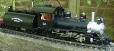
PICT0018.JPG
 
I made some home-made current collectors for the bogies on the tender, and this seemed to help for a while, but after some less than satisfactory running earlier this year, I bought a couple of tender bogies from Bachmann USA which are intended for the Mining Mogul, and which have ready made current collection with suitable wheels.

However, I have long complained about Bachmann's failure to use flywheel mechanisms. They're of no benefit to DCC users, nor for battery power, but for track power they are de riguer in the smaller scales, so why not include them in the larger scale designed for outside use where current collection is as much of, if not more than, an issue.

Dismantling :mad:

I don;t intend to list every screw and piece to be removed, because I'd inevitably get it wrong, but after removing the cab, and then undoing anything is sight, you will eventually end up with a chassis and boiler which have a number of wires keeping them joined. Having removed the base plate from the chassis, you can locate two screws (one either side) which are basically connector terminals. There are only two colours of wire - red and black - so it's safe to undo these and let go. You will also need to pull the small pins off the long brass current collector strips, and this will allow the body to be free.

Even with the wires removed, the motor is a close enough fit in its original location, so there;s no chance of getting a flywheel on it in its current position.

You will also need a double shaft motor, so we need to get the rear axle out; this requires removal of the hexagonal crank pins on the rear and centre axles - no more valve gear dismantling is necessary.

The gear box has a long, locating pin through it that goes right through the chassis, and this needs removing. I used a large clamp with a 40mm nail and, by serendipity, pushed it out the correct way - it is only knurled on one end, and from memory that is the right hand side, so push from the left. I rested the jaw of the clamp on the chassis side, clear of the pin, and it popped out easily.

Next remove the wheels ................... next time.
 
I have to apologise, I'm a bit short of piccies, but, the wheels.

Bachmann 10-wheeler wheels are in two halves. the metal part and an outer cosmetic plastic cover. The only giveaway is that the balance weights are only moulded in the plastic outer. Once the motor / gearbox /driving axle with wheels is out of the chassis, you can see how to gently prise out the plastic insert from the driving wheel - gently and slowly, by starting from the back of the balance weight. get too excited, and the plastic cover will split (don't ask me how I know this).

This will then reveal the screws that fix the wheel to the axle and remove.

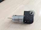
Once the wheel is off, the motor gearbox will look almost like this - this photo is with the new double shaft motor in place.

Undo the two screws closest to the motor, the gearbox will then ease off the mounting block, which can then be removed from the motor with two more screws.

PXL_20240906_142609016.jpg
 
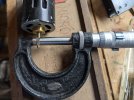
Now the fun begins - having removed the motor, you need to measure the shaft diameter. Mine was 2.3mm, and while there's no reason to doubt that other Annies will be the same, it would be sensible to check if you're doing this to an earlier, standard version of the 10-wheeler.

The fun bit is finding:
  • A new, double shaft motor suitable for 12 - 24v with 2.3 mm shaft
  • A flywheel for 2.3mm shaft
To be fair, the motor voltage isn't that critical as Bachmann locos with Mashima motors tend to only use about 10 volts when running at a scale speed of 30 ish mph. However, the motor does need to be large enough to have a bit of grunt.

In the UK, MSC models have a JH Motor which would be adequate, and Slater's Plastikard have a flywheel for 2.3 mm shaft - but ................ the diameter is 29 mm and you have to mount it on the motor shaft after the motor / gearbox / axle has been located in the chassis.

Pull the worm off the old motor with a model flywheel puller, and press the worm onto the new motor shaft (gently in the vice did it for me) but make sure that the motor is dead perpendicular to the jaws of the vice before applying pressure. I also had to cut approx 10 mm of the worm end of the shaft to make it match the old one.

PXL_20240904_122735596.jpg
 
Now we have the excitement of putting things back together.

The first question is how to angle the new motor with its flywheel. As I saw it, there were two options.

1. Angle it forwards and upwards, aiming it above its original mounting position. This will need a bit of cutting both to the chassis and the undertray - all possible and maybe even preferable as it allows for added weight over the driven axle.
2. Angle it backwards and just past the vertical. This means that the undertray remains untouched, but it requires construction of a stay to hold the motor in position.

Both options will require hacking the existing weight about - or starting afresh with a new weight.

I went for option 2 as I am bone idle and it meant less work :emo:

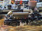
PXL_20240909_095220341.MP.jpg
 
The motor / gearbox needs to have the wheels re-fixed before the unit can be located in its new position, as the bearings fit to the stub axle on the inside of the wheel (for insulation purposes) and not the axle direct.

Once located, re-assembly can start

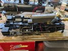
PXL_20240909_121710423.jpg
 
The motor / gearbox needs to have the wheels re-fixed before the unit can be located in its new position, as the bearings fit to the stub axle on the inside of the wheel (for insulation purposes) and not the axle direct.

Once located, re-assembly can start

View attachment 332662
Very useful set of posts. Thanks for posting, I think I have one of these chassis to put into my Tralee and Dingle 2-6-0 that uses an original 1980’s Big Hauler chassis
 
Very useful set of posts. Thanks for posting, I think I have one of these chassis to put into my Tralee and Dingle 2-6-0 that uses an original 1980’s Big Hauler chassis
The original Bug Mauler will be different - from recollection, it is a lot easier to dismantle >:)
 
Further thoughts.

The flywheel is very effective - shut the power off and the loco runs for 12 - 18" at least (Yeah, OK, I haven't measured. just guessed) but it'll certainly do the business.

I'm not sure why, but with the weight just touching the motor casing, my Helmsman controller kicked out with a short (obviously a bare wire or touching the weight as well) I glued a piece of card on the end of the weight and all was good. Someone else might cut the lead weight a bit more accurately :oops:

Having found that, after getting the motor wires rigged so that loco and tender all power the beast in the correct direction, the front light was only working in reverse, I took the headlight wires direct to the now collector board and reversed them - all good. So I then decided, as I don't smoke :emo: to simply ignore the two switches in the smokebox, snip the wires, tuck 'em up out of the way, use a connector on the headlamp wires allowing easy separation of body and chassis (which hopefully I shall never have to separate again :devil:) and leave it all wired direct. by removing the slide switch from the circuit, that removes another potential electrical weakness :cool:

I suppose we shall now see a rash of upgraded Big Hauler 4-6-0s >:)>:)
 
The original Bug Mauler will be different - from recollection, it is a lot easier to dismantle >:)
Ok good to know, my problem will be getting the chassis out of the body and fitting to the new one as after all these years I forget how it all went together. Probably near or over 3 decades ago now.
 
Eventually the short was traced to the brass contact strips within the chassis touching the sides of the gearbox. I don't think that this was the result of the modification, although with the gearbox reversed, there's more metal to be touched. I wrapped a bit of insulating tape around the brass strips at the appropriate place.

What I did notice though, was that, having reversed the gearbox, the final drive gear was the opposite side of the chassis to the moulded housing in the chassis cover. I'm not sure if it actually touched the cover, but I noticed a small pile of grease. It is possible, with a suitable diameter grinding disc on the Dremel, to extend the hollow without perforating the plastic - it probably leaves it wafer thin, but it's only there for protection rather than strength.
 
Last edited:
Damn fine Rhino....
I may just hack one of my Annie fleet....The problem is of course..I have customised the detail and weathered the one that would benefit o_O
 
Great info, thanks Rhinochugger Rhinochugger

I share your thoughts about the quality of the Bachmann 4-6-0 Anniversary - decidedly cheap and cheerful compared to LGB and Piko. Though the 4-6-0s are a good way of acquiring a large tender loco without breaking the bank. Plus my kids love the Wild West aesthetic.

I have a one which I converted to DCC using a £5 secondhand 1.5A OO decoder as an experiment to see what could be achieved on a tight budget and whether it would go bang. Many hundreds of hours of use later and it's still running fine.

Its slow running would probably be improved by adding a DIY stay alive. I've done that for my 0-4-0 steeple cab and it's made a big difference.
 
Years ago I added a decoder to run track powered DCC to my Annie. I never had any issue with taking it apart, rewiring it and then reassembling it. I did have one issue with the chuff sensor shorting so I just timed my Zimo decoder to create the chuff from the decoder and not use the Bachman sensors. I ran this engine after sitting on the shelf for over 5 years and it was flawless running outside on my 20 year old track. For pulling power I like my LGB moguls much better than the Annie.
 
Years ago I added a decoder to run track powered DCC to my Annie. I never had any issue with taking it apart, rewiring it and then reassembling it. I did have one issue with the chuff sensor shorting so I just timed my Zimo decoder to create the chuff from the decoder and not use the Bachman sensors. I ran this engine after sitting on the shelf for over 5 years and it was flawless running outside on my 20 year old track. For pulling power I like my LGB moguls much better than the Annie.
DCC helps with track power as there is a constant higher voltage through the rails. Bachmann motors tend to draw low volts - 10 volts is typical of a train running at about a scale 30 mph, so simple DC requires much cleaner track, hence the improvement with a flywheel.
 
Back
Top Bottom