idlemarvel
Neither idle nor a marvel
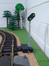
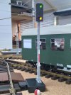
I bought a couple of these a while back and they have been sitting on my desk waiting to be fitted to my layout. 56135 is a two aspect red/green entrance (Einfahrt), exit (Ausfahrt) or block signal. Being Scale 1 (1:32) they are smaller (height 220 mm) than the LGB (RhB) 2 aspect red/green signal but more realistic in appearance for German railways, and about half the price.
 www.maerklin.de
They also do set 56136 which has two signals, a three aspect red/amber/green Hp0/Hp1/Hp2 and distant signal Vr0/Vr1/Vr2.
 www.maerklin.de
I'm not sure how well they would fare outdoors, probably not very well IMO.
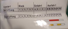
The signals come with instructions and a self adhesive sticker sheet for the red/white stripe on the signal mast, and various numbers for the signals. These conform to the German signalling system for block, entrance and exit signals, which vary according to the track number and direction of travel - "counting direction" (Zählrichtung) or "opposite direction" (Gegenrichtung) - what Brits call "up" and "down" lines.
The signals have LED lights which can be operated with up to 19 v DC (or 16 v AC - this is Märklin). The LED lights have three wires, red, green and a yellow (common). The LEDs have protective resistors.
I wanted to operate these signals from a Massoth switch decoder, which can be configured to operate lights instead of motors, using CV 51-58, The two outputs of each Massoth switch decoder port alternate between -ve voltage and + common, so if you are controlling two LED lights you only need two wires to the lights. The Märklin signals have three wires, but by using two diodes you can reduce that to two wires.
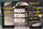
I have a habit of changing my indoor layout every few months, so I wanted these lights to be free-standing and attachable to the track, like LGB semaphore signals. I got some of these project boxes which are roughly the size of LGB point motors:

I drilled a 3 mm hole on the top to pass the wires through, and then screwed the mast to the top half of the box. The block connector shown in the previous picture was superglued to the top half of the box, and excess wires covered with black insulating tape. To connect the signal to the track, an LGB 5071 cable holder was used, hooked over the bottom half of the box and held in place when the top half is clipped on, hence the cut-out in the earlier picture. The end result is shown below:
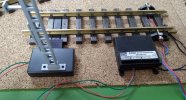
The red and green wires are connected to port 2 of the switch decoder (black not the standard blue because I painted it!) which is configured to continuous output at full track voltage - I run at 19 v . If you run at higher voltage you can adjust the output voltage with CV 71-74.
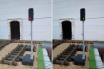
Here is the signal in operation:
Color Light Home Signal | Märklin
The signal changes from red (Hp0) to green (Hp1). It has LEDs for lights. 16 volts operating voltage. The signal comes without a mechanism. The universal r
They also do set 56136 which has two signals, a three aspect red/amber/green Hp0/Hp1/Hp2 and distant signal Vr0/Vr1/Vr2.
Color Light Home and Distant Signal | Märklin
Set consisting of a home signal with one each green, red, and yellow LEDs to indicate the signal conditions of stop (Hp0), proceed (Hp1), and proceed slowl
I'm not sure how well they would fare outdoors, probably not very well IMO.
The signals come with instructions and a self adhesive sticker sheet for the red/white stripe on the signal mast, and various numbers for the signals. These conform to the German signalling system for block, entrance and exit signals, which vary according to the track number and direction of travel - "counting direction" (Zählrichtung) or "opposite direction" (Gegenrichtung) - what Brits call "up" and "down" lines.

The signals have LED lights which can be operated with up to 19 v DC (or 16 v AC - this is Märklin). The LED lights have three wires, red, green and a yellow (common). The LEDs have protective resistors.
I wanted to operate these signals from a Massoth switch decoder, which can be configured to operate lights instead of motors, using CV 51-58, The two outputs of each Massoth switch decoder port alternate between -ve voltage and + common, so if you are controlling two LED lights you only need two wires to the lights. The Märklin signals have three wires, but by using two diodes you can reduce that to two wires.

I have a habit of changing my indoor layout every few months, so I wanted these lights to be free-standing and attachable to the track, like LGB semaphore signals. I got some of these project boxes which are roughly the size of LGB point motors:

I drilled a 3 mm hole on the top to pass the wires through, and then screwed the mast to the top half of the box. The block connector shown in the previous picture was superglued to the top half of the box, and excess wires covered with black insulating tape. To connect the signal to the track, an LGB 5071 cable holder was used, hooked over the bottom half of the box and held in place when the top half is clipped on, hence the cut-out in the earlier picture. The end result is shown below:

The red and green wires are connected to port 2 of the switch decoder (black not the standard blue because I painted it!) which is configured to continuous output at full track voltage - I run at 19 v . If you run at higher voltage you can adjust the output voltage with CV 71-74.
Here is the signal in operation:


