LGB track cleaning loco not working

The mechanic

Registered
Country flag
Hello everyone,

I have an LGB 20670 (yellow) track cleaner. Recently it has stopped working and "shorts" across the track. I am supplying 20v and it is drawing in excess of 4.5amps! (I have a current-limiting power supply and deemed this to be sufficient to "prove" a short without "over-cooking the loco!" Note, the "short" exists no-matter what position the internal selector switch is set to.

I have removed both the drive wheel unit and the cleaning wheel unit and tested them. Both function normally on around 14v. Drawing much less than 4.5amps!

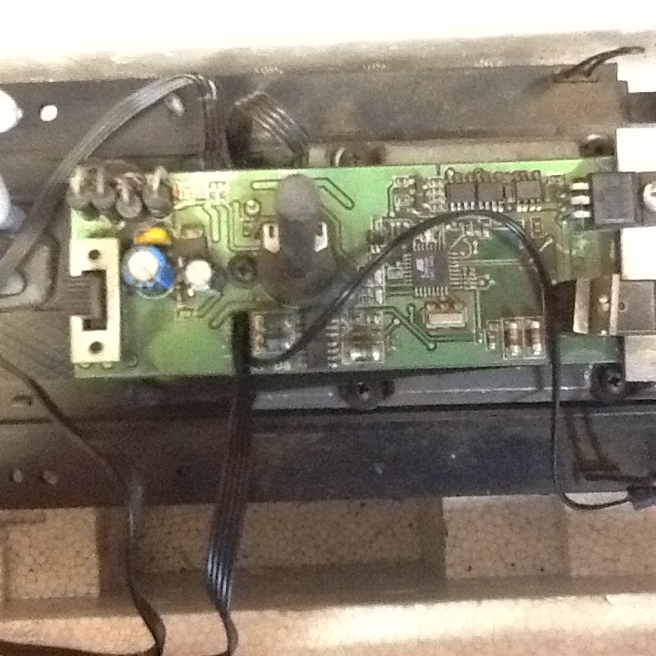
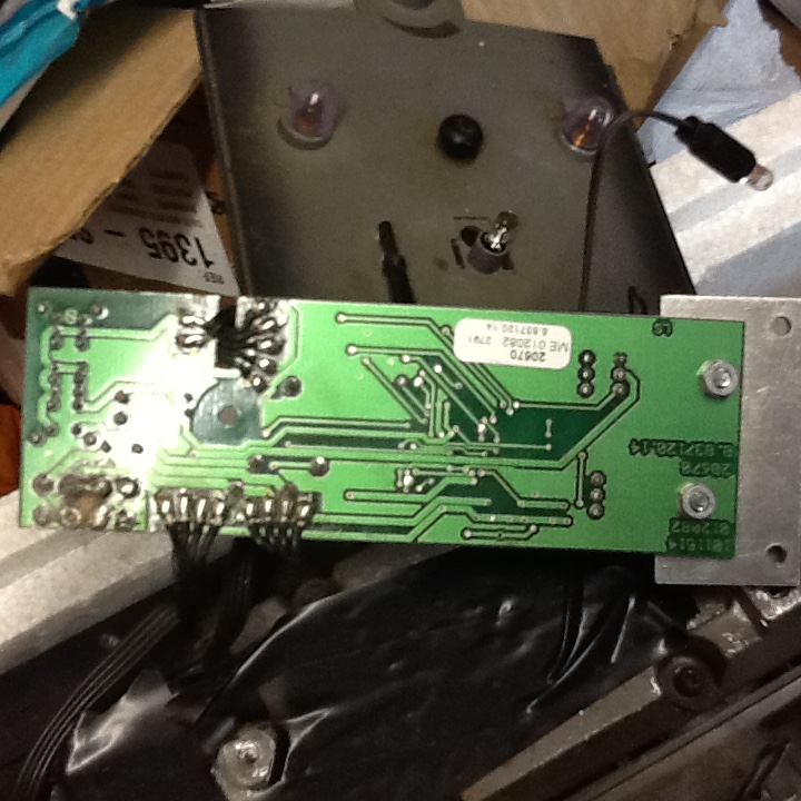
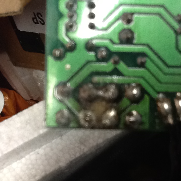
This lead me to suspect the control board. When I removed the housings, I found that one of the four black components (diodes?) to the corner of the circuit board, had become detached from the board and there was a noticeable burning of that corner of the board. I suspect that the back side had come into contact with the metal loco weight and arcing had been occurring. I have soldered the loose component but the "short" is still there. - there doesn't look to be any other noticeable visible damage to the board see photos below...

Does anyone have any experience of remedying this issue? Is it something that can be done easily? Are reconditioned boards available in the UK and from where?

I am asking this as I am running out of ideas as to a remedy.

Hope someone can help me?

Thanks

Dave
 

Attachments

  • image.jpeg
    image.jpeg
    161.7 KB · Views: 0
  • image.jpeg
    image.jpeg
    203.6 KB · Views: 0
  • image.jpeg
    image.jpeg
    157.7 KB · Views: 0
The device most likely became shorted and overheated and melted the solder.

You state that it drew over 4.5 amps.... was that before or after you opened it, sounds like before.

Based on that assumption, when you opened it, was the component completely physically detached? If it still draws 4.5 amps with that component (which is most likely a FET power transistor) then another component is also likely damaged.

I'd probably look for a new board, or remove all the electronics and add a new DCC decoder. (or are you running DC?)

Barring that, you might replace all 4 FETs

Greg
 
Try Paul at P&s Hobbies in York.. He can sort it with parts.
 
Probably not worth the time, effort and cost to repair it, from the scenario given, untold future problems could occur, the better and economic option is to source a replacement:

LGB E129813 Replacement Board for Track Cleaning Loco
Previous LGB part number - ME012082


Or a new replacement compatible unit.


Last edited:
I have found many LGB engines that had the input bridge diode fail and they short. For the dollar cost I always try to find the shorted diode and change it.
 
In this case they appear to be FETs based on the number of pins.

Whether they are FETs used as the input bridge, or the motor drive FETs, I cannot say for certain, but based on the 4 typical radial lead diodes at the upper left corner, I would say they drive the motor and are indeed FETs used as FETs in an H bridge configuration.
 
213064_82e0d991980e24944c163fe0a5dd0cb3.jpeg
 
Top-left corner of the picture re-posted by Greg, are four diodes as a bridge rectifier in the input..

Looking at the picture of the other side of the board.. There is a 'naff' looking solder joint - Look's like the wire of the diode with a ring of flux, then the solder on the pad..


You say the motors test OK out of the loco?
Does this test include the cleaning wheels, connected to the cleaning motor? - You get 'strings' of plastic, from the cleaning wheels, collect around the axles.. Once this cools and goes hard, it locks the cleaning motor solid. You get a high current-draw, and loss of 'magic-smoke'.


Being 'Techie':
I would remove the four diodes, and put pure DC (watch the polarity!) into the board from a regulated, current-limited, bench supply. WITHOUT the motors connected.
If that works:
Connect the drive motor for the loco, and see if that works..
Then check:
Cleaning motor (with wheels connected, but outside of loco. - Does it run? How much current does it take? See note about plastic-string' round axles. .. ..
If that works, connect it to the board, and try it..

If all that works, then spend on four new diodes, and fit them..

If the board (alone) is drawing 'amps', then either one of the replacements listed above, or a Massoth decoder. - There is a 'How-to' on their site.

PhilP.
 
I think it is highly unlikely the 4 input diodes are damaged, but you can test them in place with a meter on the ohms scale. If damaged you can replace them.

I would test the 4 diodes, rather than remove them, less stress on the board, hard to remove parts and put back in.

As Phil asked, does the board draw 4.5 amps with the motors detached?

If so, unless you are an electronics engineer or very advanced technician, I would replace the board.

Greg
 
Simple, just switch on for 10 seconds or less and then switch off. 90 watts has to be dissipated as heat somewhere.

If the wires to the PCB get hot it's a short on the PCB, if the diodes get hot it's the diodes.
 
In debugging damaged circuitry, if you want to repair it, I would advise against continuing to apply power, solid state electronics fry pretty fast, and you are likely to cause even more damage. The tools to investigate are what anyone would have if they were to physically repair the board, i.e. if you have a soldering iron, I would bet my bottom dollar you have a multimeter.

Greg
 
Well everyone, I thank you for all of your input.

With your comments in mind and having some spare time due to holiday etc, I did a little research on top and discovered that the suspect components are "Schottkey" diodes. Exact replacements where obtained from a trader on eBay (no connections, just a very satisfied customer), I can supply details if anyone else is interested.

On removing the diodes from the board (you need a decent sized soldering iron as these diodes are substantial and sink heat rapidly), and closer examination under a glass, it was found that three of them were indeed cracked right through. The remaining diode was the only one remaining serviceable, although at £4 for twelve, I replaced all four on the board.

The board was reconnected to the locomotive wiring loom and power applied to the pickups....... Hey presto! Apart from all of the locomotive light bulbs being blown and therefore not working, (a result of the diode failure perhaps?) the drive unit and cleaner motor worked perfectly! ... I am well-pleased with the repair which now means my tracks can be once more cleaned. Incidentally, when running in track cleaning mode, with both motors running on around 10.5volts, the loco draws 0.4amps, which I don't think is too bad given its weight! This increases to 0.55amps at 13.5volts, but by then it's screaming like a banshee and I will never run it like that anyway. The only other departure from standard issue was that I wired the cleaning motor to rotate the same way as the driving wheels as this tends to stop the cleaner unit "bouncing" when moving forwards even though it may reduce the cleaning efficiency slightly?

I am now looking for some replacement bulbs (or even better, LED's) for the amber flashing lights and the white spot lamps, interior lamp and reverse lamp having checked voltage at the bulb holders of each lamp.

Best regards

Dave
 
Last edited:
I found that the unit I had would barely run with the cleaning wheels running at 12 volts. Bouncing is caused by out of true wheels, you can true them up a few times before they wear out and need replacing.

Good deal on replacing the input diode bridge, now don't do it again ha ha! Seriously you must have shorted something to destroy them, so watch carefully for repeating that situation.

Greg
Hi Greg,
According to the handbook that comes with the loco, the on-board DCC chip allows you to vary the start up voltage etc. Now, I only run on analogue DC voltage and have no means of "interrogating" the on-board "electrickery" but I suspect that at some point this has been set so that the unit runs on a lower voltage (perhaps?) - or am I grasping at nettles here? I did notice that the manual speed control "pot" does absolutely nothing to the speed of the cleaning wheels when it is turned, so maybe this has been set by the DCC control? - I don't know, but the loco works and that is good enough for me at the moment.

With reference to the initial failure mode of the diodes, I think the amount of microscopic brass filings which where covering the board didn't help too much? - need to remember to clean the loco out each time after use in future!

Dave
 
Last edited:
With reference to the initial failure mode of the diodes, I think the amount of microscopic brass filings which where covering the board didn't help too much? - need to remember to clean the loco out each time after use in future!

Worth cleaning the 'plastic-string' from around the cleaning wheel axles, as well.. - This set's hard, and the next time you try to run it, you find the cleaning wheels are locked-solid.

PhilP.
 
Ah, that explains why the speed of the cleaning wheels doesn't change when I turn the pot then?!

Thanks for that Greg, I was a bit mistified why this should be the case. I'll check the loco wheel speed next time I run it.

Now, as mentioned above, the next challenge is replacing all of those blown light bulbs!

Does anyone know if I can use pre-wired 12v LED's as a replacement? Or is the lamp voltage higher than this when the track cleaner is running and therefore any replacement LED's will require a higher value resistor than that used for 12v supply?

If this is the case, does anyone know off-hand what value resistor should be used in each LED circuit?


Dave
 
I think the bulbs run from track voltage, so if you run more than 12 volts I would advise matching your max voltage on the rails.

To me, the lights are more decoration than actually lighting the track, or a real warning to real people (in terms of the beacon).

LEDs are easy, use an LED calculator, although you should know the current rating of your LEDs

Perhaps this page will help:

Greg
 
Standard bulbs for the 20670 track cleaner are 5V, original LGB ref 68511 (bag of 10)
Champion Phil, as I need some for my own TCL.

I've asked Muns if he has any in stock....
 
Back
Top Bottom