Now I have the old LGB boards, I am in the process of trying to add them to my Bachmann. I appreciate I should probably just ditch them, but they work and in the interest of experimentation, and with (hopefully!) some guidance, I would like to give a go at installation over the festive break! I have seen elsewhere on here people using similar boards, but as mine look different, I thought I should start a further thread. Hope that is ok.
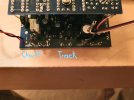
Shown on the photo are the pins that used to go directly to the track for power. My plan is use r/c battery for the loco. My plan would be to run wires from the pins and splice them to the wires going to the motor. I assume that although that voltage would be variable as speed is increased (as it was under track power) it would be ok, with the 9v battery taking care of the lower end? I also assume that it doesn't matter about polarity? I did think about connecting the pins direct to the battery, but then it would never turn off - unless I put an additional switch on.
The pins marked chuff are what used to go to the sensor in the LGB mogul. I have seen some great tips elsewhere on using hall sensors and magnets on tender wheels, and I am going to have a try at that. May I ask what hall sensor and magnets best, where you would suggesting purchasing, and which pins would go to which part of the sensor? I did think about getting one of these for ease but again, I wouldn't know which pins would go to which wire ? Massoth 8242030 - Clock Set Standart Axle New 4251102686869 | eBay
I think I have figured out the whistle/bell activation.
As usual, any suggestions would be welcomed. Thanks.
Attachments
Last edited: