LGB 20900.1 and CV programming

Andrew_au

Registered
Country flag
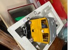
Have an old LGB 70255 starter set (digital starter set, 2x digital locos, MTS-1). The diesel loco is labelled 20900.1.

I also have a Roco z21 XL central station & Decoder Pro.

Using either Decoder Pro or the z21 computer app (not the iPhone cab app), I can read/write all CVs for the steam loco, and also for a Massoth eMotion L added after-market to an LGB 28002. This is using "direct mode". However, for the diesel, I can only read/write successfully if I switch to "register mode". In this mode, I can only read CVs 1-8, and can only write registers beyond 8 by using indirection through registers 5 & 6. Sometimes it appears to read the other registers, but if I change or refresh anything the values become gibberish.

Does anyone have any advice for working around / fixing this? Although the set is second hand, I can't see anything to suggest that the two engines (diesel & steam) use different electronics, so it surprised me that one works and one doesn't.
 
I wonder if your diesel has the really old 55020 decoder (or, I believe, the first iteration of the 55021)?
These were very limited, with only a small number of CV's that you could manipulate.

Your easiest route, may well be to find a 55021, or Massoth equivalent, and swap the decoder.

PhilP
 
All the starter set MTS locos I have come across have onboard decoders. Maybe someone has changed it.
 
Pop it open and post a photo of the decoder. If it is an early release (Lenz) then I would suspect it uses a 55020 which may only support register mode programming. Onboard decoders only came into effect once Massoth electronics were used.
 
I'm assuming the daughter-board on top is the decoder. Unless it's built-in?
 

Attachments

  • YellowDieselDecoder.jpg
    YellowDieselDecoder.jpg
    289.6 KB · Views: 0
  • YellowDieselElectronics.jpg
    YellowDieselElectronics.jpg
    241.5 KB · Views: 0
The top board is the decoder. The bottom board has 4 switches and when off you add the decoder to make the engine work. If you remove the decoder then the 4 switches must be on. this is how LGB isolated the motor and track power wires for DC to DCC conversion. Also note most LGB decoder upgrades disabled the 3 and 4 position switch in the cab.
 
It identifies as an LGB 55021. Other numbers on PCB: ME-v2.0, 01 4200,10131 42
CV7=28, CV8=123

If I read in register mode, I get sensible values for CV1-8, albeit seems to take a long tie to respond. If I use direct mode, I get nonsense back for some CVs. For example:
CV12345678
Reg12220102555428123
Direct4411025521123

The values in the "reg" mode are what I see implemented when driving.

Other examples: CV29 reads via direct as 1, when it's actually set to 6. Etc. The odd thing is that the 'bad' values are consistent and constant. CV 1 always reads 44, CV 29 always reads 1, etc, even if I write other values.

It might be just that I have a broken decoder, but it's very strange that it all works correctly except for direct-CV mode. I can (and have) programmed the high CVs using LGB CV6/CV5 indirection.

Note that this issue would not have shown up for the original owner, since they only had access to the old LGB MTS handsets which use register mode writing (and AFAIK no read-back).
 

Attachments

  • DecoderBottom.jpg
    DecoderBottom.jpg
    190.3 KB · Views: 0
OK, this is very odd. I moved the 55021 from the yellow diesel to my 28002 (which is an adventure in and of itself). I can now read all the CVs in direct mode.

I do have some strange issues:
  • Horn and/or bell seem to sound at random times when doing CV reads & writes (which implies the F1 output is being driven up/down)
  • I still can't get the parallel mode -> serial F1 interface working (topic for other thread).
CV7=28
CV8=123
CV106=192

Could this be a power supply issue? Would a decoder fall back to register mode if there was insufficient current being supplied? I don't quite understand why a decoder would not program correctly in one loco but work in another.
 
Another strangeness. These are the pin receptors for the 55021 on the yellow diesel...

YellowDieselDecoderMount.jpg

If you compare that to a 55021 pin layout, we have:
  • Row 1: Rear lights, Voltage+ (missing)
  • Row 2: Front lights, Voltage+ (missing)
  • Row 3: Motor green, Motor yellow
  • Row 4: <?>, F1, Voltage+ (missing)
  • Row 5: Track white, Track brown
Pin marked <?> is not labelled in the 55021 manual, but is labelled "Ground" in the 55020.

In contrast, the 28002 does not have the GND pin, but has Voltage+ pins on rows 2 and 4.
 
Back
Top Bottom