It's getting better all the time

Rhinochugger

Retired Oik
Country flag
The big challenge with battery powered locos is to make the switch(es) and the charging socket accessible but concealed.

My next project is to convert my 2-6-2 with a scratchbuilt chassis.

But by far the biggest challenge is to make the wiring and installation neat and tidy ::) ::) ::) ::)

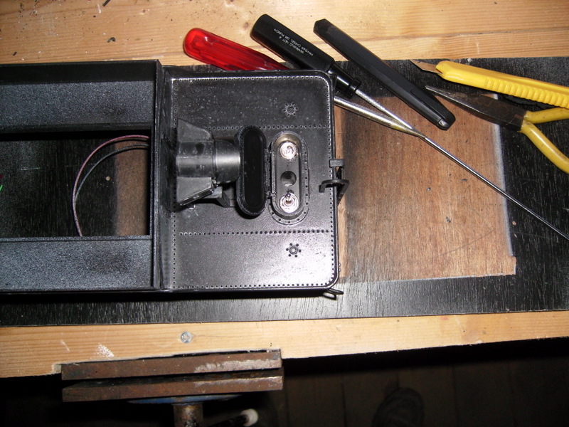
The 2-6-2 has, for a couple of years, been running with a K27 tender. These tenders have an oval shaped water filler hatch, and in the centre there is a fixing screw hole.

I reckoned that i could get a sub-miniature toggle switch for on/off mounted one side, and the charging socket the other :D :D

It was b***** fiddly, but worth it :-X :-X


Attachments

  • PICT0002.JPG
    PICT0002.JPG
    187.3 KB · Views: 57
To date, I still use a trailing battery R/C car. I have too many locos to afford separate equipment for each of them. I still remove the battery to charge them, as I have spares to replace a dis-charged battery.
 
Tony Walsham said:
Hi Rhinochugger.

You could always make up something like this. http://www.rcs-rc.com/content/9007/bik-k27/

Yes, Tony- like it. My home made coal load (I bought he tender body shell as a spare part from Bachaman) isn't quite as easy to slip on and off as the standard item.

I think I'm going to fill the body of the tender with 18v Nmh sub-C batteries, as the loco uses a large 7-pole Buhler motor ??? ??? ???

Why the large motor? it was going cheap at the time ;D ;D ;D ;D
 
Right, now, technical question

I used the Mtroniks speed controller last time, and they also do one that can cope with up to 20v.

The controller has a separate on/off switch, so on the Banta crewcab, because i was using a push switch that was double pole, I used the one pole for switching the live feed to the battery, and the other pole for switching the controller on/off. it works OK.

Here, I'm only using a SPST switch. Will it matter leaving the controller switch permanently on, as the juice will be cut by the main on/off switch?

................or have I lost my marbles :o :o :o
 
I have recently completed two projects where I could not find a suitable position for both switch and charging socket. The answer was to use a switching charging socket - I generally use 2.1mm power sockets. When I plug in the charging lead, the internal contacts disconnect the battery from the radio receiver. Therefore when I want to switch off the radio receiver I simply put in a dummy plug made from plastic of a suitable diameter with a 2.1mm hole drilled in the end - cheap, simple and space-saving.

As to removing the battery to charge it, this was not an option with my new Accucraft A3 as the only suitable space for a battery is in the tender behind the water bath - only accessible by dismantling the tender.
 
Most of the SPDT DC coax sockets you describe such as this,
P0622.gif
have a potential on the metal body of the socket.
It is a good idea to mount them on insulated material so that there is no possible conflict with any pre-existing potential on the loco body, which some metal bodied locos do have.
 
Tony
That is a very valid point that I forgot to mention. On my last two installations I was very keen not to drill or cut into the models and a plastic panel just inside an existing opening to mount the socket met that requirement and provided the insulation. In the case of the A3, the model water fill cover, which opens, provided the ideal location for the socket and has the advantage of hiding the socket while the locomotive is running. In the earlier installation I mounted a plastic panel between the tender frames and angled down slightly to allow the plug to be inserted from below the buffer beam - again out of sight when running.
 
davidarf said:
I have recently completed two projects where I could not find a suitable position for both switch and charging socket. The answer was to use a switching charging socket - I generally use 2.1mm power sockets. When I plug in the charging lead, the internal contacts disconnect the battery from the radio receiver. Therefore when I want to switch off the radio receiver I simply put in a dummy plug made from plastic of a suitable diameter with a 2.1mm hole drilled in the end - cheap, simple and space-saving.

Yep, that's a method that I've heard of before.

My problem is understanding how to wire the socket in switch mode ::) ::) ::) so I've only used two tags with them.

(At this point Tony Walsham rolls his eyes heavenward muttering that a little knowledge is dangerous O0 O0 O0 )
 
They be very clever little sockets.
Can be wired up in a variety of ways.
I retain battery positive to the pin and use the SPDT switch to control the battery negative circuit.
 
Rhinochugger said:
Yep, that's a method that I've heard of before.

My problem is understanding how to wire the socket in switch mode ::) ::) ::) so I've only used two tags with them.

(At this point Tony Walsham rolls his eyes heavenward muttering that a little knowledge is dangerous O0 O0 O0 )
I can never remember which contact is which on the socket and so I always start by putting in a plug without it's cover and then using my testmeter to check for continuity. As Tony says, I also always use centre pin for plus. Therefore my first test is to identify which tab on the socket connect to the centre pin of the plug - that is the plus to both battery and radio (via fuse etc). With that sorted, I next check which of the other two tabs is connected to the outer on the plug. That is the battery negative. The remaining tab on the socket is the negative to the radio.
 
davidarf said:
I can never remember which contact is which on the socket and so I always start by putting in a plug without it's cover and then using my testmeter to check for continuity. As Tony says, I also always use centre pin for plus. Therefore my first test is to identify which tab on the socket connect to the centre pin of the plug - that is the plus to both battery and radio (via fuse etc). With that sorted, I next check which of the other two tabs is connected to the outer on the plug. That is the battery negative. The remaining tab on the socket is the negative to the radio.

All the commercially available chargers I have seen with already installed 2.1mm plugs are designed for +ve on the centre pin so it would be fairly unwise to wire the socket any other way! I have, however, seen one transformer/rectifier with a 2.1mm plug, looking just like a battery charger, which had a centre -ve. It was designed to be used with a garden light fitting. I'm not totally sure how such a potentially dangerous device came about, but suspect a bit of Chinese design. Lasted about as long as it took to find the wire cutters; I'm still using it but with coloured RCA plugs in a water tight container.
 
Most R/C transmitters have +ve to the pin but I believe JR transmitters have a battery charge jack wired -ve to the pin.
Some of the multi connector lead kits have both types of plugs.
 
I have one of the Ansman chargers (not made any more I believe) which will adjust to whichever polarity the socket is wired ;) ;) ;)
 
Update on last:

The Ansmann charger doesn't appear to be compatible with a socket that is wired for switched use.

I have been installing a small battery pack in one of my Accucraft cabooses: converting from track pick-up to battery.

Apart from blowing the bulbs with 4.8v (I had assumed that the bulbs were 5v as per the loco headlamps) when I tried to charge the battery pack, the circuit breaker could be heard tripping. this drove me mad; I re-built the simple circuit board to no avail.

I have bee playing with my test meter - no light dawned.

Then, reading back on the thread, I started working on the charging sockets when they were disconnected from the chargers. Then I tried them connected to the chargers.

The Ansmann cause a trip, the other charger does not.

The Ansmann is still OK with charging sockets that are only wired with two wires (not switched)

Weird or wot (or should that be wired) ??? ??? ???
 
Back
Top Bottom