Installing sound and pulsed smoke into LGB 20271 Heidi

Distrackted

Registered
16 Apr 2017
48
7
67
Swansea, UKE
Best answers
0
Country flag
Here are some notes and pictures regarding a recent upgrade I did to my LGB 20271 "Heidi" locomotive. The project was reasonably straightforward, although as I am a bit old school and prefer switches to programming locks, I did have one issue.

I ended up having to use three toggle switches, in addition to the factory "cab" switch to enable all three decoders (onboard, sound and smoke) to be programmed in isolation of the other two.

It turned out that since I was using simulation mode from the sound decoder to pulse the smoke, simply cutting off power to the sound decoder was not enough to isolate it. With power to the pulsed smoke generator on, and power to the sound decoder off, there was signal passing back through the simulation connection sufficient to "blip" the speaker connected to the sound card and cause all kinds of cv read errors from the smoke generator decoder.

Adding a switch to break the "simulated pulse" connection between the two solved the issue completely, and all the decoders could be read and written flawlessly. However, it wasn't enough just to interrupt the ground wire, which I thought would be sufficient! I also had to interrupt the signal wire. This required a double pole single throw switch adding further to the project complexity.

I wan't really happy with all the shiny switch levers sticking down below the frame, but covering them with black heat shrink went a long way to making them less obvious.

Removing the body from the frame on this locomotive is easy as all the screws are visible without removing the motor block and running gear. I was able to leave all the original pieces of the locomotive in place, simply drilling holes for sound in the boiler support plate, and in neat rows in the frame on either side of the mounting block.

Due to limitations to the allowed amount of test in a single post, I will put the detailed project description in a reply post.......


Here is the finished locomotive reassembled:
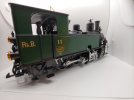
20210829_090337.jpg

and here is a view of everything mounted in place (sound board and enclosed speaker - sorry no pictures of the round pulsed smoke generator in the smoke box):
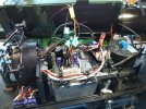
20210828_120001.jpg

and another view of the items in place:
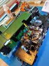
20210824_120922_HDR.jpg

and here is a view of the holes drilled in the boiler support which was left in place:
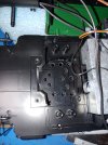
20210815_160030.jpg

with the speaker and enclosure screwed in place:
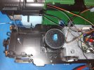
20210815_180631.jpg

here is the volume control mounted sideways on the inside of the frame with nylon hex standoffs:
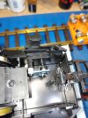
20210818_193221.jpg

and a side-on view of the volume control knob:
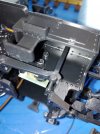
20210818_193253.jpg

here is a view of how the reed switches were mounted in a diy protective sheath:
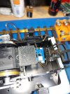
20210818_194217.jpg

and another view with the reed switch board in place:
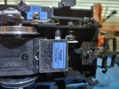
20210821_175602_HDR.jpg

here is an inside-cab view of the two toggle switches required to fully isolate the smoke generator:
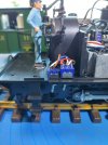
20210828_114500_HDR.jpg

and a view of the same switches from below:
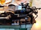
20210828_152701_HDR.jpg

here is the inside=cab view of the toggle switch used to isolate the sound board:
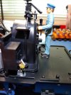
20210821_175756.jpg

and a view of this switch from the underside:
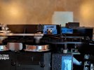
20210828_152712_HDR.jpg
I
 

Distrackted

Registered
16 Apr 2017
48
7
67
Swansea, UKE
Best answers
0
Country flag
Here are further details to above...

LGB 20271 Upgrade to Sound and Pulsed Smoke – August 2021


The LGB 20271 is a digital non-sound locomotive equipped with a large On-board decoder and standard smoke generator.

To do the upgrade, the standard smoker was removed.

The following items were added:

  • Massoth eMotion S sound decoder with RhB Heidi sound project loaded.
  • Massoth 8415001 pulsed smoke generator for round boilers
  • Massoth 8242010 eMotion volume control
  • Massoth 8242020 eMotion reed switch board
  • 1 SPDT miniature toggle switches (to isolate sound decoder / turn sounds off)
  • 1 SPDT miniature toggle switches (to isolate smoke decoder / turn smoke off)
  • 1 DPDT miniature toggle switch (to prevent loopback between smoke and sound decoders)
  • 1 Visaton K 50 WP 2” speaker (with custom made cylindrical ABS sound enclosure)
It was decided to use simulation from the sound card rather than install a hall-effect pulse generator due to the complexity of the running gear on this locomotive and difficulty in removing the motor block to install a hall sensor. This is also the reason the reed switch board was mounted in an external enclosure rather than within the motor block.

Physical:

  • 7 screws holding the body to the chassis were removed. For one of the rear screws, the small oil tank must be gently pried off for access.
  • The two wires leading to the smoke generator were unplugged from the onboard decoder. The smoke stack was twisted 90 degrees counter clockwise and removed from the smoke box. The smoke generator was then pushed up out of the smokestack.
  • The smoke box was removed from the boiler by tilting it upwards and carefully releasing the tab at the back top of the smoke box.
  • The pulsed smoke generator was inserted into the smoke box using the guide rails inside the smoke box to align with the tabs of the smoke generator. The generator was pushed in just far enough for its output opening to align beneath the hole for the smoke stack. Replacing the smokestack and twisting it back in locked everything into place. Very easy.
  • A piece of ¼ “ ABS plastic large enough for the sound decoder was affixed to the weight in front of the onboard decoder. The sound decoder was screwed down to the ABS using small screws and standoffs.
  • The volume control was mounted to the chassis in a large cavity underneath the rear of the locomotive with the knob facing out the side and mainly hidden by the toolbox, but accessible from the left side of the locomotive with a small flat screwdriver. The wires were run up through the cab, through the side of the firebox in the cab, and forward through the bulkhead to the electronics in the boiler.
  • The single pole switch was mounted just to the left of the firebox within the cab with the switch lever pointing down near the rear of the running gear. This switch is mounted logically on the right side of the locomotive close to the volume control. The purpose of the switch is to cut off track power to the sound decoder to prevent inadvertent CV changes when setting CVs on either the smoke decoder or onboard decoder. It also allows the sound to be shut off when desired.
  • The double pole switch was similarly mounted on the right side of the locomotive. One half of the switch is used to break the black ground wire between the sound decoder and smoke generator. The other half of the switch breaks the clock connection wire between A3 on the sound card and the pulsed smoker. This prevents loopback interference when setting CVs on either decoder otherwise isolated from track power. This switch should be set to off when programming either the smoke generator or sound decoder in isolation.
  • The second single pole switch is mounted just aft of the double pole switch on the right side of the cab. The purpose of this switch is to cut track power to the smoke generator and also to isolate it when changing CVs on either of the other two decoders.
  • To install the speaker, the boiler support plate covering the original speaker grill of the locomotive was retained. A series of holes were drilled in this plate to allow sound to pass downwards. In order to enhance the sound volume, a custom-made cylindrical enclosure was fabricated from ABS sheet goods. The enclosure screws to the boiler support plate from underneath, holding the speaker to the plate by pressing down on the speaker’s rim. The enclosure is airtight and does not interfere with reassembling the locomotive. It greatly enhances the volume and clarity of the sound.
  • The reed switch is mounted at the rear of the motor block. A sheath into which the reed switch slides snugly was made from ABS. The sheath is attached to the rear extension of the motor block with a single small screw. Te switch can be slid in our out without undoing the screw and removing the sheath. The 3 pin cable from the reed switch was routed through the cab like the other wires.
Electrical:

  • The weight block was removed by undoing four screws. This allowed the main connector on the motor block to be accessed and unplugged. A 20 gauge white, and 20 gauge brown wire were soldered onto the back of the existing track wires at the connector. The plug was reinserted and the weight block reinstalled.
  • Two additional 20 gauge brown wires were soldered onto the new brown track wire, with one wire being run to each single pole toggle switch.
  • White 20 gauge wires were run from the other switch terminals and connected to one of the track power input wires of each of the sound and smoke decoders,
  • The other track power wires of the two decoders were then connected to the white track power wire coming from the motor block plug to complete the circuit. Thus power to each or both of the added decoders could be switched off as needed.
  • The three wires from the reed switch were soldered to the back of the sound decoder. The centre wire was soldered to the pad labeled ground, while the two outer wires were soldered to K1 and K2 respectively (order not important). Track magnets will close each reed switch depending on which side of the track each magnet is on. This will trigger the sound assigned to each switch in the CVs.
  • The 3 pin cable supplied with the smoke generator was plugged into the smoke unit. The wire consists of red, brown and black conductors. The red wire is not used and was cut short and insulated to prevent any contact with metal or other components. The brown and black wires were cut approximately mid-cable and additional 2-pin wires were spliced into each. These 2-pin wires were run back to the two sides of the two pole switch to allow current flow to be interrupted in both the black and brown wires when required. The end of brown wire is soldered to the pad labeled A3 (function output 3) on the sound decoder which provides the simulated pulse clock signal. The black wire is soldered to the “ground” pad also used for the reed switch.
  • With the sound decoder firmly mounted again, the 2-pin speaker cable was plugged into the socket with a picture of a speaker adjacent.
  • The 3-pin cable from the volume switch was plugged into the socket with a picture of a potentiometer adjacent.

  • CV Programming:

  • This locomotive has three decoders as described. Information on all of them is included with this upgraded locomotive. All of them are products of Massoth, Germany, although the onboard decoder is an LGB labeled MTS unit.

  • To program the onboard decoder, turn all of the added toggle switches to off while leaving the original switch in the cab in either position 3 or 4.

  • To program the sound decoder, place the original switch inside the cab to position 1 (leftmost) which cuts power to the original onboard decoder. Also turn both the toggle switches for the smoke generator to their off positions. Ensure the sound decoder toggle switch is in the on position (left side of loco).

  • To program the smoke generator, place the original switch inside the cab to position 1 (leftmost) which cuts power to the original onboard decoder. Turn the toggle switch for the sound decoder to the off position. Also make sure the 2 pole toggle switch (front most) on the right side of the locomotive is in the off position. Ensure that the toggle switch for smoke generator power is on (aft switch on right side of loco).
Important Settings:

All decoders are set to primary address 3, parallel mode and 28/128 speed steps. The latter settings are compatible with LGB MTS3 and Massoth and Piko Navigator handsets. Reading and writing control variables is best done with the Massoth PC Module and Massoth Service Tool software.

In order for pulse simulation to be enabled on the sound decoder CV 114 should be set to a value of 30.

In order for the external volume control to be used CV 200 (total volume level) must be set to a value of 255.

Operation (MTS / DCC):

For full light, sound and smoke operation, ensure that the cab switch is set to position 3 or 4, and that all external toggle switches are turned on.

A list of the sounds actuated by each function button is included with this modified locomotive. F9 turns lighting on and off. F7 activates the pulsed smoke function. Pressing F7 again deactivates it.

Track magnets will trigger the whistle and bell sounds.

Operation (Analog / DC):

When running on an analog layout, the chuff sounds can be heard and the whistle and bell sounds can be triggered by track magnets. The headlights operate directionally.
 

craigwrdouglas2

Registered
29 Jun 2021
87
19
44
Scotland
Best answers
0
Country flag
This is fantastic, thanks for sharing this.

I'm half way through fitting sound and smoke to my Rhaetia at the moment, so it's a very timely article indeed.

The version that I have from the set has some internal differences - it comes with an 28 pin mfx socket in my case and a slot for the speaker in the underside of the boiler, which has holes to let the sound out..
 
Last edited:
  • Like
Reactions: 1 user

Distrackted

Registered
16 Apr 2017
48
7
67
Swansea, UKE
Best answers
0
Country flag
This is fantastic, thanks for sharing this.

I'm half way through fitting sound and smoke to my Rhaetia at the moment, so it's a very timely article indeed.
All the best with your project! Hope it goes smoothly. I have found it to be hard to find much information on working on LGB locomotives on the internet, so I am happy to share my experiences. It occurred to me after the fact that perhaps a couple of diodes may have worked to replace that double toggle switch to isolate the smoke generator. I'm not too knowledgable on electronics so perhaps some other members might have thoughts on this?