Help Needed - Decoder Wiring

David1226

Registered
Country flag
The first thing we need to establish is that I am completely clueless when it comes to model locomotive digital wiring. I need help (some may say that I am way beyond help) as it is a complete mystery to me.

I have a LGB 20790 Corpet Loupet which was bought some years ago, second hand, from eBay. It had been fitted with an after market chip, presumably by the previous owner. The loco never ran properly but I never bothered to do anything about it at the time. When run on DCC there was a loud buzz coming from it. I experimented with the dip switches in various positions but nothing made any difference. I was of the opinion that the decoder itself was faulty.

Also, some years ago, I acquired three brand new LGB 55027 loco decoders at a very good price. I have now decided it's time to get this loco up and running. I have stripped out the old decoder and attempted to wire in one of the 55027. The manual supplied with the decoder does not help me identify which colour wire goes where. I started by cutting off the 10 pin connector as this does not fit the existing board in the loco.

I have wired the track pickup and motor wires and the loco runs nicely back and forth along a length of track. I am at a loss to know which coloured wires need to be connected to power the front and rear lights and the smoke unit. There are no other functions of interest.

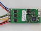
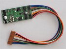
Fig 1. LGB 55027 Decoder
P2070001.JPG

P2070005.JPG

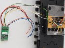
Fig 2. The LGB 55027 wired into the loco pc board for track power and motor control.
P2070002.JPG

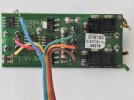
Fig 3. The old decoder

P2070004.JPG

Fig 4. The six pin connector that connects the old decoder to the loco pc board.
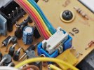
P2070003.JPG

Any advice/assistance would be much appreciated.

David
 
So first, I would obtain the manual so you can see what wires are for the lights and smoke unit. If someone does not have a link, I can email to you.

On the new board, the 3rd from the top left (deep orange?) is the rear light, and the 3rd from the bottom (orange) is the front light, but I don't know the loco to tell you where the common is, i.e. the voltage of the lights in your loco.

The smoke must be connected to one of the 6 function outputs, but then again I don't know your smoke unit.

I'm sure there are people to fill in the blanks.

Greg
 
Attached is the 55020 manual. Diagrams 1 and 2 appear to provide the info you seek about what wire goes where. Presumably it should be feasible to splice the requisite cables from your 55027 into the 6 wire connector making a simpler connection to the existing main board.
 

Attachments

With respect to Ralphmp his link is to the manual of a different decoder than that in your image.


You said "I have wired the track pickup and motor wires and the loco runs nicely back and forth along a length of track. I am at a loss to know which coloured wires need to be connected to power the front and rear lights and the smoke unit. There are no other functions of interest."


I hope the following is of help with the decoder in your photo.

Take a look at this.
and click on manuals.

Note on page 4 it states "Decoder + is the common connection for lights and auxiliary functions F1 – F6" this means one side (doesn't matter which as light bulbs and the smoke unit aren't polarity sensitive) of all of your lights and smoke unit need to be connected to Decoder + terminals. The other side wires from the lamps go to their appropriate terminals and I suggest you use F1 for the smoke unit's other wire.
Page 5 shows the terminals you need to use with your decoder.
Please double check the bulb and smoke unit voltages are set appropriately before powering up.
 
Last edited:
I understood that Ralph provided the wiring on the "from" decoder (he clearly states the model number of the original), and that combined with the 55027 manual would be the "road map" to switch the wires. I had hoped someone would post the 55020 manual actually.

The only thing now is to verify that the 55027 "outputs" can handle the current of the smoke unit, the smoke unit voltage, and verify the voltage of the lights.

Greg
 
Only trying to help - my assumption (yes, I know that to assume makes an ass out of u and me) was that as David already has the 55027 manual, by referring to the one for the 55020 it should be possible to determine what wires need to go where. The diagram on page 10 of the 55027 manual explains the purpose of each wire attached to the decoder. Apologies for any confusion caused.
 
That's the way I saw it too Phil.

It seems the 55027 has a max of 300 ma per "output" is that enough for the smoke unit? Are we even sure of the voltage on the smoke unit?

Greg
LGB 5v. smoke generators consume 291 ma so the 300 ma will be sufficient for the smoke unit as long as it's the only device connected to the terminal.
 
Actually the specifications on pg 10 of the manual state each function output can go up to 0.8 amp with a total for all functions and lighting outputs limited to 1.3 amps. The two lighting outputs are limited to 300 mA each.

I'm going to speculate that F2 is typically used for non-pulsing Seuthe smoke units based on the picture on pg 4 of the manual showing a LGB 10 pin decoder interface board. I'm guessing the smoke unit plugs onto the two pins labelled F2/6.5V on the interface board. The interface board supplies the 6.5V which sinks through F2 and the common ground between decoder and interface board on pin 9 of the decoder interface. Perhaps someone that actually has one of these in a LGB steam loco can confirm or deny.
 
Last edited:
Many thanks to everyone who has supplied information and suggestions, by referencing it all I would appear to have sufficient information to work out the required connections. I shall proceed slowly. It will not be a quick job as, apart from the electrical update, there are a few physical modifications and some painting required.

David
 
Just to be sure and to satisfy your concerns re DCC setup, why not use a choc block to verify that your wiring is correct? That way you can run temp setups device/choc block/chip, then solder up the wires when you are happy. Oh not forgetting some heat shrink if you solder 2 wires together or you could leave the chic block as coupled, sufficient space in the Corpet. This was how I wired things up in my early days doing a job like yours.

My further thoughts are that the colour code will be your friend for the majority of wires, LGB were pretty good with standardising them.

EDIT Oh just remembered, the dip switches should be all off. However be aware that some boards have 2 sets of dip switches, but your loco as shown only has 1 set.
 
Last edited:
why not use a choc block to verify that your wiring is correct?
Jon

Yes, that was my intention. Although I have soldered the track power/motor connections, as they are set in stone, I shall use a choc block for the other connections.

David
 
Jeeze, I swear they were grayed out before, yes your manual is newer, and they upped the current on the function outputs.

I would guess 0.8 amps would be fine on the Seuth track powered (18v) units, and maybe even the 5-6v ones.

Sorry Phil, will get my brain transplant tomorrow!

Greg
 
Where is the manual you are referring to?
Just an aside, Märklin/LGB has many manuals that can be similarly downloaded. You only need to search on the product number to bring up a page similar to the 55027 page Neil provided the link for. Most items since around 2006-2007 have at least some info available.
 
Back
Top Bottom