alasdair555
Registered
I'm sure there are already posts on topics similar to this, but I'm struggling to find one that explains the options available clearly.
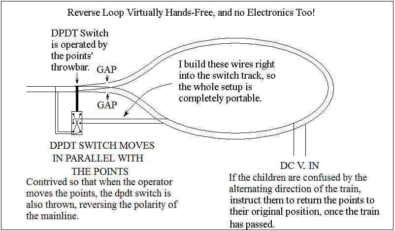
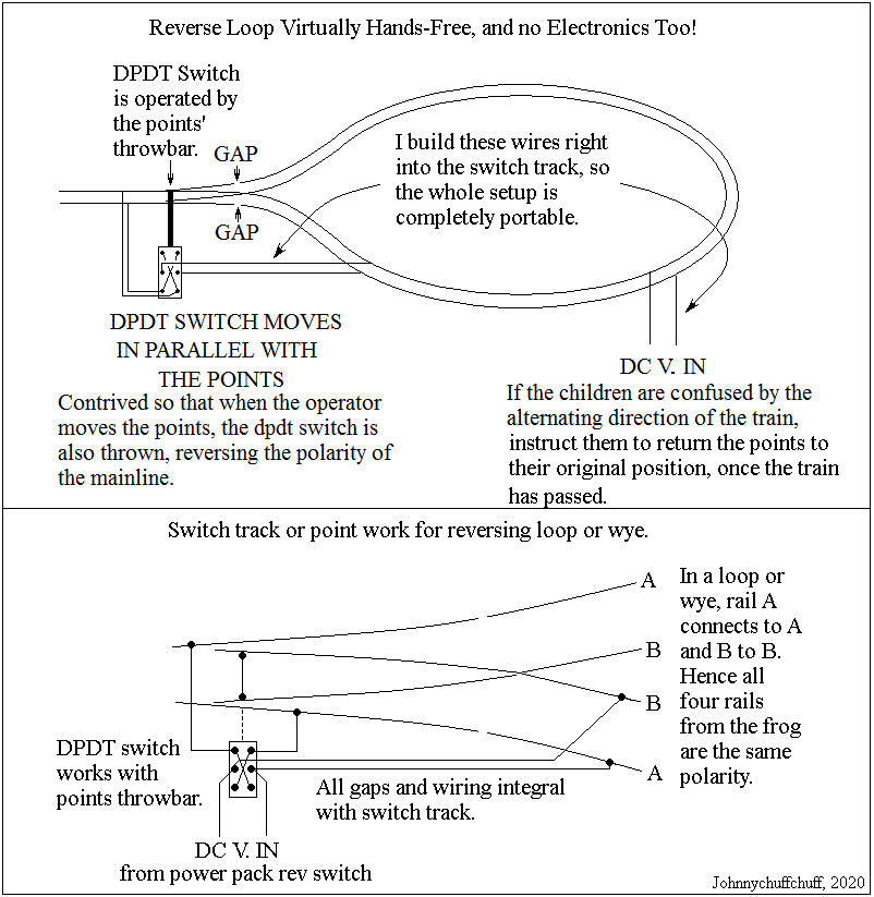
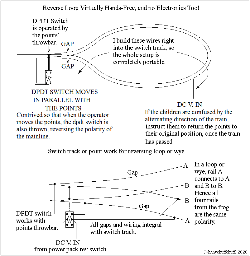
In summary I'm planning a simple single track reverse loop, the railway needs to be operated by young children, and we've got DC track feed.
As a result I can't expect them to stop/start and switch points in perfect sequence, so would prefer either an off the shelf solution, or a simple wired solution which requires little if any intervention!
This is my other post with mor detail on the overall track layout etc.
Many thanks in advance for all suggestions,

 www.gscalecentral.net
In summary I'm planning a simple single track reverse loop, the railway needs to be operated by young children, and we've got DC track feed.
As a result I can't expect them to stop/start and switch points in perfect sequence, so would prefer either an off the shelf solution, or a simple wired solution which requires little if any intervention!
This is my other post with mor detail on the overall track layout etc.
Many thanks in advance for all suggestions,
Under 5s and G scale
Made some progress on the layout today, cut some supports for the railway from a chimney pot, but used up 2 angle grinder cutting disks in the process, so I'll need to wait a little while before I can do much more on that front. On the plus side the remainder of the line now has profiles, and so...
www.gscalecentral.net


 )
)")