Airbuspilot
Registered
Hi
I am working with a friend with a partially completed LGB garden railway, neither of us have any experience of DCC. I have programmed a loco on my N scale layout but using different equipment, on Monday I tried for the first time to program an accessory decoder using his ZIMO equipment. The MX32 instructions talk about Loco programming with virtually no mention of accessory programming.
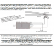
The turnout decoder we are using is a ZIMO MX820D with an LGB 12010 turnout motor. The unit is presumably a motor unit rather than a solenoid type as it only has two wires.
I am using the ZIMO MX10 command station with the ZIMO MX32 handset.
Following the MX32 instructions I was able to change the address of the decoder from 3 to 50, the green ACK message came through and the 50 was in red (not sure if that's relevant?)
Setting the MX32 to a new blank page I was able to read the accessory address as 50 by pushing the TP key so I assume I was successful.
However when I connected the decoder to the track the MX 32 did not recognise the decoder. Existing, already programmed turnouts on the handset, have coloured icons, the "newly programmed" turnout was a blank square.
I assumed the MX 32 would recognise the new decoder without further action?
Having entered a new address / CV with the MX32 is it necessary to save the entry in some way to the MX32?
The info on page 13 of the decoder instructions is very confusing (for me!)
As this turnout is a motor rather than a solenoid I also need to make further CV entries to provide a longer actuation time?
#513 is the decoder address = 50
#545 = 0 - control by #1 push button on MX32
#515 (presumably I can ignore 516, 517, 518) = switch time - 30 = 3 seconds.
W key saves new info to decoder?
Do I need to make a further action with the handset?

If there is anyone with ZIMO experience I would be grateful for some help.
Thanks
Robin
I am working with a friend with a partially completed LGB garden railway, neither of us have any experience of DCC. I have programmed a loco on my N scale layout but using different equipment, on Monday I tried for the first time to program an accessory decoder using his ZIMO equipment. The MX32 instructions talk about Loco programming with virtually no mention of accessory programming.
The turnout decoder we are using is a ZIMO MX820D with an LGB 12010 turnout motor. The unit is presumably a motor unit rather than a solenoid type as it only has two wires.
I am using the ZIMO MX10 command station with the ZIMO MX32 handset.
Following the MX32 instructions I was able to change the address of the decoder from 3 to 50, the green ACK message came through and the 50 was in red (not sure if that's relevant?)
Setting the MX32 to a new blank page I was able to read the accessory address as 50 by pushing the TP key so I assume I was successful.
However when I connected the decoder to the track the MX 32 did not recognise the decoder. Existing, already programmed turnouts on the handset, have coloured icons, the "newly programmed" turnout was a blank square.
I assumed the MX 32 would recognise the new decoder without further action?
Having entered a new address / CV with the MX32 is it necessary to save the entry in some way to the MX32?
The info on page 13 of the decoder instructions is very confusing (for me!)
As this turnout is a motor rather than a solenoid I also need to make further CV entries to provide a longer actuation time?
#513 is the decoder address = 50
#545 = 0 - control by #1 push button on MX32
#515 (presumably I can ignore 516, 517, 518) = switch time - 30 = 3 seconds.
W key saves new info to decoder?
Do I need to make a further action with the handset?

If there is anyone with ZIMO experience I would be grateful for some help.
Thanks
Robin
