Hi,
I am a newbee to this site and have recently returned to railway modelling by building a layout in my backyard.
Having operated on analog dc up until now, I am currently considering moving to DCC control. However a friend of mine also having recently moved to DCC control is experiencing unexplained failures on different decoders fitted on a variety of locos.
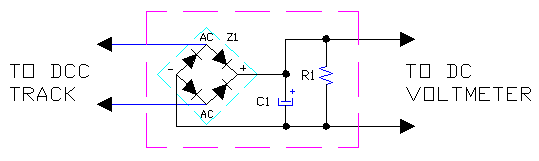
The common factor here would seem to be the LGB MTS central station. The LGB transformer output checks OK but the question arises how to check the central station output (i.e the track voltage).
I am an electrical engineer with some experience of data transmission systems as applied to power system monitoring, but the complication here is the data signal is also the loco power. So some questions;
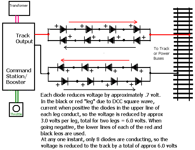
1. How is the loco powered when data is not being transmitted. Nosing around the web I find references to Bi-polar dc which is also referred to as ac.
2. Is this sinusoidal or an alternating square wave.
3. If I connect an oscilloscope to the track what should I expect to see?
4. What is the maximum peak to peak the Massoth decoder expects to see.
5. What is output from the decoder to power the motor. Variable rectified dc or PWM square wave?
I am a newbee to this site and have recently returned to railway modelling by building a layout in my backyard.
Having operated on analog dc up until now, I am currently considering moving to DCC control. However a friend of mine also having recently moved to DCC control is experiencing unexplained failures on different decoders fitted on a variety of locos.
The common factor here would seem to be the LGB MTS central station. The LGB transformer output checks OK but the question arises how to check the central station output (i.e the track voltage).
I am an electrical engineer with some experience of data transmission systems as applied to power system monitoring, but the complication here is the data signal is also the loco power. So some questions;
1. How is the loco powered when data is not being transmitted. Nosing around the web I find references to Bi-polar dc which is also referred to as ac.
2. Is this sinusoidal or an alternating square wave.
3. If I connect an oscilloscope to the track what should I expect to see?
4. What is the maximum peak to peak the Massoth decoder expects to see.
5. What is output from the decoder to power the motor. Variable rectified dc or PWM square wave?
") Many thanks for the responses gents.
Many thanks for the responses gents.