Brixham
No buffers were hurt at this sign
Phew...I thought this would be quick.....
All I can find is this:http://www.bromsgrovemodels.co.uk/dcc.htm?Submit=Digital+Control
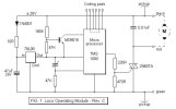
Just an image showing a 3 wire DCC decoder made by ZTC
I can't find any proper info at all!
I did find a link to a site...but then there wasn't anything of use.
Malcolm
All I can find is this:http://www.bromsgrovemodels.co.uk/dcc.htm?Submit=Digital+Control
Just an image showing a 3 wire DCC decoder made by ZTC
I can't find any proper info at all!
I did find a link to a site...but then there wasn't anything of use.
Malcolm
 ecoders" / Loco modules were indeed 3 wire.

")