Close Coupling Unit

3 minutes of fame

3d printing, electronics and trams
Country flag
From my fevered mind comes another little design...

Walking around the Garden Railway Show, I chatted to a trader about some of his laser cut coaches and the length of drawbars needed to get them around tighter curves.

It set me thinking that if it works at 00, it will probably work in G!

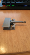
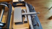
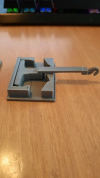
This is my first prototype, ready to fit to my W&U coach:
1625303948576.png
1625303966640.png
1625304187318.png
 
What is the reasoning on the "hard lock" at maximum angle?

Also it would seem you would want 2 springs inside.

Greg
No, it doesn't need any springs, the weight of the load will happily pull it straight again and the shape of the keeper plate means it will always return to the straight ahead position. It's based on the concept of the Keen close coupler for 00 stock, but I've redesigned the keeper plate and yoke to suit larger stock and the amount of movement required.

The angles are set so that the hook cannot travel outside of the buffer beams. It would be easy to re-design the plate to allow more movement, but this will get my W&U coach with 40mm overhangs comfortable around 2'6" radius curves. Once I got the "production" version finished, I will take some pictures of the unit in action :)
 
What will return it to center under no load? Just the angle of the cars? Would seem that some tension would be needed.

I get that, but then what if you are pushing cars? The buffers save you?

Ahh, I missed the divergence would be limited to not foul the buffers, of course. Sorry.

I keep forgetting you guys have that additional feature!

Greg
It's the shape of the keeper plate that keeps the angle constant under load and compression. The aim is to avoid buffer lock on curves and the concept works extremely well.
 
My friend used one of the Uk varieties in 00, he found that there was some ‘stickiness’ with the operation due no doubt to the lack of quality control that would be present with the Fleishmann HO variety. But I would imagine that such imperfections would be less crucial with your larger 3d printed ones.
 
My friend used one of the Uk varieties in 00, he found that there was some ‘stickiness’ with the operation due no doubt to the lack of quality control that would be present with the Fleishmann HO variety. But I would imagine that such imperfections would be less crucial with your larger 3d printed ones.
I've printed these in some nice shiny PLA and my printer is extremely well calibrated, so stickiness in operation is not an issue. I've printed off the "production" parts now and I'll post some pictures once they are fitted.

I need to make up the linkages as well. My thoughts are that these will be solid soldered chain links, so it will look like an authentic but will prevent buffer lock and pushing.
 
Very nice work, but i have a suspicion you want to calibrate your printer, i think you have some "under extrusion" or "flow" or "fill in"issues, sorry.

With best regards Igor
 
Very nice work, but i have a suspicion you want to calibrate your printer, i think you have some "under extrusion" or "flow" or "fill in"issues, sorry.

With best regards Igor
The gaps are due to the fill just being set at 0 degrees to the main axis of the model. For the production parts, I use 0, 45, 90 fill pattern and this prevents the gaps. I was previously printing some wooden parts for a station building and wanted the grain to run in 1 direction only, so the setting was not ideal for more complex parts.

Just increasing the extrusion would cause too many other issues like poor dimensional accuracy and holes becoming irregular. Trust me, the print settings are pretty much spot on :)
 
Back
Top Bottom