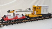
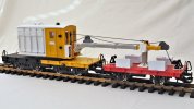
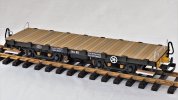
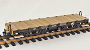
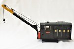
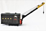
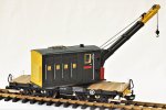
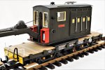
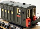
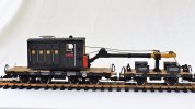
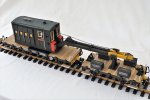
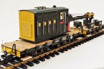
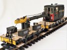
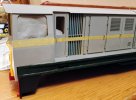
Claptowte Railway - Engineering Department Travelling Crane 'TITAN'

David1226

Registered
24 Oct 2009
7,889
7,897
74
Abingdon, Oxfordshire
Country
United-States
Best answers
0
Country flag
Part 1 of 5

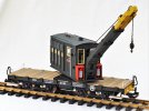
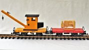
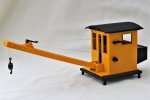
To add variety and interest to the Claptowte Railway rolling stock, I had always intended to add a travelling crane, with associated match truck, to support the crane jib while in transit. To that end, over the years, I had collected various donor vehicles and components to construct such vehicles. The crane is based on the LGB Toy Train crane, with an additional Toy Train stake wagon to increase the length of the frame and decking as it was my intention to mount it on a pair of bogies.

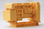
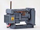
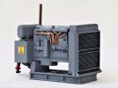
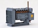
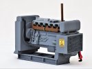
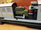
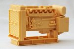
Some years ago I acquired a resin casting of a diesel generator, from a trade stand at an exhibition. I believe it to be a copy of a plastic model that was supplied as a wagon load (x3) on a USA Trains flatbed. I thought of using it to use as a wagon load myself until I had the idea of using it as the power source for the travelling crane. The casting itself, was not top quality, being full of blow holes, but used inside the bodywork of a crane, these faults would not be obvious, indeed, most of the time not seen at all.
dig 220929015.JPG

This is the resin casting of the diesel generator.
dig 221021008.JPG

dig 221021009.JPG

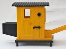
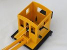
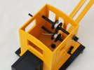
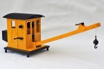
This is the starting point of the actual crane conversion, the LGB Toy Train crane body, removed from the stake wagon on which it comes mounted.
dig 221021003.JPG

dig 221021004.JPG

dig 221021002.JPG

dig 221021005.JPG

dig 221021006.JPG

dig 221021007.JPG

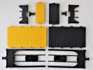
I actually began the conversion of this model with the underframe and decking. I took the Toy Train stake wagon on which the crane body had been mounted and added a second stake wagon. Both wagons were dismantled down to their basic components. The stakes, and the two wheel bogies and wheels, on which the wagons had run, were consigned to the spares box. Of the four brake pipes, two were put aside for use on the new body and the other two followed the wheels into the spares box.

In order to create a new longer single body, to mount onto bogies, I used a razor saw to cut midway between the 4th and 5th stake pockets on both bodies, so that when the bodies are brought together, the spacing between the stake pockets, along both sides, are maintained. Be sure to cut off the ‘non balcony’ ends, so that when the underframes are cut to length, to match the decking bodies, the fixing points for the footsteps are retained.
dig 221021001.JPG


I cut the buffers from the short lengths cut from the underframes. The buffers were kept and consigned to the spares box, the offcuts of decking and frame were discarded.


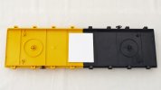
The two shortened decks were then glued together with a butt joint. The underside of the join was reinforced using a section of 2.0mm plasticard.
dig 230215006.JPG

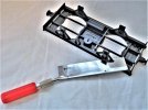
I took the underframes and cut off the ‘W’ irons and brake support.
dig 180227006.JPG

I cut out the various tanks, retaining the large cylindrical tanks and discarding the rest.
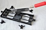
dig 180227007.JPG

I then cleaned up the frames and tanks with files and wet or dry paper.
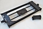
dig 180227008.JPG

I then offered up each of the underframes to their respective bodies and cut these to match the body lengths. I glued the two haves together and used plastic strip to strengthen the joints.

Using various suitable thicknesses of plasticard, I built up the underside of the underframes to the appropriate height, finishing off with a large rubbing plate for the bogies. Holes were drilled into which plastic tube was glued to form the pivots for the bogies. LGB Toy Train footsteps were added from the spares box. I attached Garden Railways Supplies (GRS) etched brass lamp irons to each buffer beam. I glued a plasticard plate across the centre of the join between the two donor halves, to further strengthen the join, and glued the pair of salvaged tanks to this.
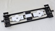
dig 221024002.JPG

I attached a pair of LGB Jackson Sharp passenger coach bogies to the pivots, using offcuts of plasticard as securing washers. The bogies were fitted with Al Kramer bright nickel plated, turned solid brass wheels, imported from the US. These wheels are standard across all of the Claptowte Railway rolling stock. The wheels are very heavy and give a nice low centre of gravity to the model. I re-attached a brake pipe to each buffer beam. I added bent handrail wire grab handles to each corner of the deck, adjacent to the footsteps. These matched the similar grab handles on the match truck. To complete the rolling chassis, I added a brake wheel to each side of the body. These were from the balcony railings of a LGB Jackson Sharp passenger coach, salvaged from another earlier conversion.
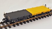
dig 230215011.JPG

David
 
Last edited:
  • Like
Reactions: 1 user

David1226

Registered
24 Oct 2009
7,889
7,897
74
Abingdon, Oxfordshire
Country
United-States
Best answers
0
Country flag
Part 2 of 5

Having completed the rolling chassis, I moved on to the conversion of the crane superstructure.

dig 230215012.JPG


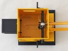
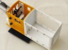
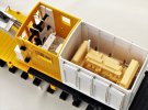
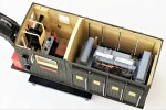
I began by removing the dummy counterweight from the rear wall of the cab, this simply unclips. I then extended the body to incorporate a compartment to house the diesel electric generator casting. The floor was a piece of 3.0mm plasticard, which was the same thickness as the floor of the original model. The new floor was scribed and grained to represent a wooden planked floor. The new floor extension was butt jointed to the rear edge of the original cab floor and the join reinforced by gluing on another piece of 3.0mm plasticard covering most of the underside of the new combined floor area.

I then cut and shaped a 2.0mm piece of plasticard to form the front wall of the engine compartment. This was scribed to represent vertical wooden planking. I carved off the window surround of the rear cab window and made sure it was sanded flush. I then glued this wall to the rear of the cab, to cover the apertures of the window and the slots that held the counterweight.

The side walls were fabricated from 2.0mm plasticard with large apertures cut out to give access to the engine. The apertures would be covered by louvre opening doors. These side walls were also scribed to represent vertical planking.

The rear wall of the engine compartment, also 2.0mm plasticard, was shaped to match the roof profile, An area of the interior surface of this wall was scribed to represent the inside surface of a louvre ventilation panel. This area was framed with 2.0 x 1.5mm plastic strip. The remainder of the wall was scribed to represent vertical planking. The outside surface of the wall had a corresponding louvre panel constructed. The panel was framed using the 2.0 x 1.5mm strip. The louvres were created by gluing in lengths of 2.0mm quarter round rod. Again, the remainder of the wall, outside of the louver, was scribed to represent vertical planking. The width of the planking was scribed to match the planking of the original crane cab.


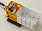
After the four sides were glued to each other, and each to the floor, reinforcing timbers were glued the length of each wall, to the interior, at floor level, and vertically in each corner, using 2.0 x 1.5mm plastic strip. Four holes were drilled along the top and bottom edge of the apertures on each side wall, at appropriate distances and heights. Into each hole was glued a cut down 3/64” cotter pin, to form part of the hinges that would support the four access doors each side of the engine compartment.

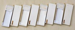
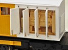
Eight doors were constructed, four for each side of the engine compartment.

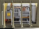
These doors were again made from 2.0mm plasticard with external framing of 2.0.x.1.5mm plastic strip. Before the framing was added, the interior surface was scribed to represent the inside surface of ventilation louvres and the outside surface was scribed to represent wooden planking. Louvre ventilation panels were added, to the top of each door, using the same 2.0mm quarter round rod, used to create the louver on the rear wall of the engine compartment. Handrails were fitted to each door using brass wire. Pins, made from the same wire, were inserted into the top and bottoms if the doors, to engage into the cotter pins, in the side walls, to form operating hinges. Door retaining hooks were made from offcuts of brass strip, salvaged from etched brass lamp iron frets, and glued to the bottom of each door. These brass strips hook over the lower edge of the side apertures, to hold them in the closed position. To open the doors, you grip the handrail, lift the door slightly on its hinges to allow the hook to clear the inside of the lower side wall, and open. To lock in the closed position, reverse the process.

dig 230215013.JPG

dig 230215014.JPG

dig 230215016.JPG

dig 230215018.JPG

Having completed the engine compartment, I moved on to altering and fitting out the original cab of the donor crane. The first thing was to remove the roof by unclipping it. This was consigned to the spares box. For ease of access, the cab body can then be unclipped and separated into two parts.

This also releases the two winding mechanisms for the jib and the hook. I modified these by cutting off the toy winding handles. The winding gear can still be used, but the appearance is much less obtrusive.

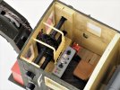
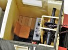
Apart from the afore mentioned winding gear, the interior of the crane cab is completely empty and as such provides a blank canvas for fitting out and detailing. I have no engineering background and have never seen the inside of a crane, I have no knowledge of the operating controls. What follows is pure imagination, helped by a couple of glasses of fine Cognac.

I shaped a thin piece of plasticard and glued it to the rear wall to cover the other side of the rear window and counterweight slots. I scribed the outline of a cab door into the otherwise plain interior. I drilled and fitted a bent wire internal door handle.

The premise is that the power to the winches that wind the jib and the hook are provided by electric motors, with power supplies by the diesel generator. There is, in any case, insufficient room in the cab to fit any complicated cog and fly wheel arrangement, so I contrived that all the motors and winding mechanisms would be concealed behind cabinet work. To simulate this I built up the area at the front of the cab floor, and up the sides to encompass the winding gear, using layers of 3.00mm foam board. I embellished it to make it look a bit more cabinet like.

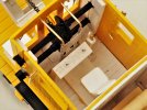
There is a hole in the cab floor through which a screw secures the body to the turntable. For the now extended body, the point of rotation is too far forward. I drilled a new hole as far back as I could in the floor, to make a new pivot point. I cut another piece of thin plasticard, the size of the remaining floor area, which I then scribed to represent floor planking, to cover the floor of the cab. I created a ‘transmission tunnel’, to run fore and aft down the centre of the floor, though which power cables could run between the engine compartment and the motor cabinets. I scribed the top surface of this to represent diamond plate. At the front end of this tunnel I crated a pair of foot pedals, using thin plasticard. These pedals control the left and right traverse of the crane.

I created a safety screen between to operator and the rotating winch drums by drilling holes in either side of the traverse pedals and in the front wall of the cab at just below roof height. I fabricated the screen using two lengths of brass handrail wire, bent to a right angle at the top, and joined by expanded aluminium mesh in front of the two winch drums.

I created a cantilever control panel with various nondescript dials and buttons, fixed to the floor, to the operator’s left. Two shortened dress making pins in the control panel represent joy stick controls for raising and lowering the jib and the hook. On the right side of this control panel I installed a mechanical hand brake, to lock the traverse of the crane in any position. I finished off the cab interior by installing a seat, for the operator, made up of odds and ends of plastic.

As stated above, I do not know how real cranes operate, but this method works for the Claptowte Railway.


David
 
Last edited:
  • Like
Reactions: 1 user

David1226

Registered
24 Oct 2009
7,889
7,897
74
Abingdon, Oxfordshire
Country
United-States
Best answers
0
Country flag
I hit a snag uploading this topic. It's a large amount of data which I split into four sections. It would appear the second section was too big to load and I had to delete part of it to get it to load. I will now have to upload the story in five parts. Unfortunately I have run out of time and will now not be able to finish it for another week, Very frustrating and unsatisfactory. Watch this space.

David
 
Last edited:
  • Like
Reactions: 1 user

ge_rik

British narrow gauge (esp. Southwold and W&LLR)
24 Oct 2009
10,701
1,244
Cheshire
www.riksrailway.blogspot.com
Best answers
0
Country flag
........ Watch this space.

David
I certainly will. This must be one of your most well-detailed builds so far. Really impressed with the opening doors to the engine compartment and the detailing in the cab. I can't imagine what will happen next but I know it will be good.

Rik
 
  • Like
Reactions: 1 user

David1226

Registered
24 Oct 2009
7,889
7,897
74
Abingdon, Oxfordshire
Country
United-States
Best answers
0
Country flag
Part 3 of 5

dig 230215015.JPG

I added a board across the cab door as a mounting point for the etched brass name plate on that side. There is no door on the opposite side, so not required here. I finished off the door by carving off the moulded door handle and fitting one made from bent wire. I reasoned that while the operator would have a view of the jib, when looking forward, through the front windows, he would not be able to see the corresponding rear overhang when traversing. To rectify this I made two rear view mirrors, from plasticard and bent wire, and fixed these to the cab side windows. Given that the crane would be required to operate in all weathers, I also made up a pair of windscreen wipers for the front windows, from scrap brass fret soldered to brass wire.

I finished off the superstructure of the crane by fitting a new roof. This was made by bending a suitably sized piece of 1.0mm plasticard, by heating it in hot water, rolling it then cooling it in cold water. Laborious, but it finally stayed the desired shape. I shaped four transverse roof trusses and glued these to the underside, to both locate the roof and help hold its shape. I drilled a hole in the centre of the cab area to fit a GRS roof vent. Above the engine compartment, I fabricated an exhaust and silencer, for the diesel engine, from bits of plastic tube and rod.

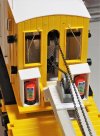
While trawling through eBay one day, I came across some exquisite model fire extinguishers. I bought a pair as I thought they would make a nice embellishment to the model, but I could not decide how or where to fit them. In the end I made up a couple of cabinets, from plasticard, and installed them of the front of the body, either side of the jib.

dig 230214002.JPG

That completes the body of the crane. The last major component was the jib. I cut off the tip portion of the Toy Train jib, and the base where it joins the crane body. I made up a new longer twin boom jib, using 3/8ths square plastic tube and various bits of plasicard and 5/16ths plastic channel. 1.0mm self adhesive pearl gems were stuck on as bolt/rivet heads. I incorporated two pulley wheels. I do not know the origins of the wheels, I have had four of them in my spares box for years. I suspect, but I may be wrong, that they are fittings from a high end curtain or window blind closing system. The last job was the replace the white thin cord ropes of the original model, with bronze coloured chain, at thirteen links to the inch, obtained from eBay.

dig 230215019.JPG

The final assembly before painting

dig 230215020.JPG

dig 230215021.JPG

The body and jib mounted on the rolling chassis and coupled to the Match Truck.

dig 230215026.JPG

dig 230215024.JPG

dig 230215025.JPG

David
 
  • Like
Reactions: 1 users

playmofire

Registered
23 Oct 2010
8,266
853
80
North Yorks
Best answers
0
Country flag
Superb model and what an exquisite attention to detail!
 

David1226

Registered
24 Oct 2009
7,889
7,897
74
Abingdon, Oxfordshire
Country
United-States
Best answers
0
Country flag
Part 4 of 5

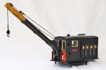
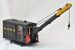
The various component parts were dismantled and, where appropriate, sprayed with grey plastic primer, then painted before final assembly. The livery is Engineering Olive Green. The signs were printed on my ink jet printer onto white card. After cutting to size, I ran a black permanent marker pen along the cut edges, to blacken them. For continuity of appearance, this was the same method that I used to sign the Match Truck and the Tool/Mess Van that I had already constructed to accompany the travelling crane.

The painted and sign written rolling chassis.

dig 230302022.JPG

dig 230302023.JPG


The body and jib.

The Electrical Danger signs were copied from the internet, downsized and printed on white card. The etched brass nameplates are from Custom Nameplate Studio.

dig 230302011.JPG

dig 230302013.JPG

dig 230302012.JPG

dig 230302014.JPG

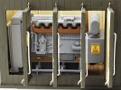
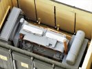
I added a plastic rod exhaust pipe to the diesel generator before it was sprayed with grey plastic primer. I left it that base colour as it appeared quite suitable. Some details were picked out in different colours and I added cooling pipes, fuel lines and power connections from various bits of wire and cable.

dig 230302001.JPG

dig 230302002.JPG

The warning signs are the same as fitted to the engine compartment doors.

dig 230302003.JPG

dig 230302004.JPG


The cab interior

Having painted the model, the cab interior was glazed. I normally use 1.5mm clear polystyrene of polycarbonate material, but I thought that would look too obtrusive in this case, so I used thin clear plastic that I believe came with a building kit. It is glued in with clear silicone glue that does not craze the material and means that the glazing can be removed if there is need of a repaint or refurbishment in the future.

dig 230302017.JPG

dig 230302018.JPG


The engine bay

dig 230302019.JPG

dig 230302016.JPG

dig 230302021.JPG

dig 230302020.JPG

David
 
  • Like
Reactions: 1 user

David1226

Registered
24 Oct 2009
7,889
7,897
74
Abingdon, Oxfordshire
Country
United-States
Best answers
0
Country flag
Part 5 of 5

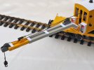
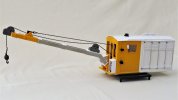
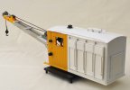
The finished crane

dig 230302025.JPG

dig 230302026.JPG

dig 230302027.JPG

dig 230302028.JPG


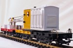
The crane complete with its Match Truck

dig 230302029.JPG

dig 230302031.JPG

dig 230302032.JPG

dig 230302033.JPG


David
 
  • Like
Reactions: 1 user

David1226

Registered
24 Oct 2009
7,889
7,897
74
Abingdon, Oxfordshire
Country
United-States
Best answers
0
Country flag
.
 
Last edited:
  • Like
Reactions: 1 user
idlemarvel

Neither idle nor a marvel
13 Jul 2015
3,136
801
Ascot
Country
Mars
Best answers
0
Country flag
Superb modelling.
 

mike

Master at annoying..
Staff member
GSC Moderator
24 Oct 2009
51,805
4,433
Rossendale
www.gscalecentral.net
Best answers
0
Country flag
Is it wrong to drewl
 

David1226

Registered
24 Oct 2009
7,889
7,897
74
Abingdon, Oxfordshire
Country
United-States
Best answers
0
Country flag
Superb modelling.
Could you please give some more detail of how you printed the signage on your printer?
I used Microsoft Word. Open a table, you only need one row. Depending on the size of the text, divide the row into two or three columns. I actually had a saved page set up from when I made the signage for the Tool/Mess Van, which had one wide column for the text and a smaller width for the wagon numbers, so I just added to that. For my signs I inserted a black background into the table and changed the font colour to white. Select the font you require, I used Arial, with the bold button added. Select the font size you require, a bit of experimentation may be required here, or type the same text in different size fonts, so you can select the size you want after printing. Centre the text in each column then type in white on black. I printed, using my inkjet printer, onto bright white card. After cutting the items to appropriate size, with a steel rule and scalpel, I ran a permanent black marker pen around the cut edge to blacken it. I applied white PVA clue to the back of the sign and offered it up to the model. When happy with its position I pressed the sign firmly into position.

The Claptowte Railway is very much an indoor railway. I have no doubt that if exposed to rain and strong sunlight these sign would not last that long on and outdoor railway, but it works for me. If they need replacing, a soak with some soapy water should remove the old sign and once the surface has been carefully cleaned up, a new sign can be applied.

David
 

ColinK

Registered
14 Apr 2017
270
140
67
Lancaster
Best answers
0
Country flag
Excellent modelling, superb crane.
 

David1226

Registered
24 Oct 2009
7,889
7,897
74
Abingdon, Oxfordshire
Country
United-States
Best answers
0
Country flag
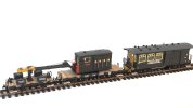
It only occurred to me recently that I did not have any photographs of the whole ensemble, match truck, crane and mess/tool van. I set about rectifying that.

dig 240201002.JPG

David
 

maxi-model

UK/US/ROW steam narrow gauge railways 1:1
27 Oct 2009
5,673
661
Bucks/Oxon/Northants area
Best answers
0
Country flag
Really nice work David. If you have one part you have to make the others for it to work.

I thought I recognised that generator. A chap was selling them, new, on eBay about 3-4 years ago. Story was a large quantity were found mislaid in a UK warehouse. They were supposed to be an optional accessory load for a Corgi truck range. Mention was made of the US connection.

The 3 I bought were all original injection moulded in kahki/black. Mine are destined for - Vale of Ffestiniog (shown), Conway Castle and a WHR generator car (with sound !). Each has or will have mods to better suit their host and application. I really love the idea of hiding major details, like you have, that needs a panel removed to see.IMG_20240204_153715_919~2.jpgIMG_20240204_153558_678~2.jpg