Cannot get second LGB 55525 decoder To work

Sloopg

Registered
Hi

Successfully installed my first LGB 55525 decoder to operate 4 turnouts. Set them up as “new installation decoder” with a “DCC” setting, using addresses 1-4 and they work perfectly. Installed a second 55525 decoder and am having issues with it. The CS2 sees the decoder and automatically added 4 more devices to the CS2. Used the same setup as the first installed 55525 ... “new installation decoder”, “DCC”. They were automatically set to addresses 5-8. Here’s the problem ... the turnouts do not operate. The turnouts and decoder are about 20’ from the CS2. My voltmeter shows that power is getting to the 55525. The decoder and turnouts that work are within 2 feet of the CS2.

All ideas welcomed.
 
Last edited:
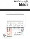
You mean 55525 presumably. Does your new one respond to addresses 1-4? I'm thinking maybe the programming didn't take. When you were programming the new addresses on your second unit did you short the programming pins and have a motor connected to port A (see diagram from manual).

Capture.JPG
 
What Dave says..

But you can chaeck the second unit as follows:

Move the suspect unit to the first location.. Connect the power and one turnout.. Does that one turnout work? - Check ALL addresses 1-8, even on the second 55575.

If it works with a 1-4 address, programming has not 'taken'..
OR
If it works in the closer location, you have a power / voltage-drop / some other wiring problem.
 
You mean 55525 presumably. Does your new one respond to addresses 1-4? I'm thinking maybe the programming didn't take. When you were programming the new addresses on your second unit did you short the programming pins and have a motor connected to port A (see diagram from manual).

View attachment 269541
Hi

Thanks for the fast response. Thanks for noting the right part # - updated original post as well.

When I installed the second 55525, I had the track power disconnected, connected the power input wires, attached the first turnout wires and then connected the tracks to the power supply. The CS2 recognized the 55525 and assigned addresses 5-8 but the turnout did not work. Used the same process for the first 55525 I installed. I did not have the loop shown above in place. I thought that the loop was needed if you were going to change the default settings.

regards
 
Just because the CS2 recognises a new device and assigns it the next addresses doesn't mean that you've actually programmed the decoder to those same addresses? It's not a decoder I've ever used, but I presume you have to do something like set a programming jumper or wire on the decoder and then fire a point command on the first new address to get the decoder to pick up that address? [edit] Ah, as per Dave's diagram in the earlier post [/edit]
 
What Dave says..

But you can chaeck the second unit as follows:

Move the suspect unit to the first location.. Connect the power and one turnout.. Does that one turnout work? - Check ALL addresses 1-8, even on the second 55575.

If it works with a 1-4 address, programming has not 'taken'..
OR
If it works in the closer location, you have a power / voltage-drop / some other wiring problem.


Thanks. Did the distance test hooking up the second 55525 to the track close to where the first 55525 is attached and connected one of the turnouts that was working with the first 55525. Same result. Next test is to uninstall the second 55525 and then reinstall it with the loop wire in place. Will connect the track to the CS2 using the PROG input. If that doesn’t work, I’ll reinstall the first 55525 and then install the second so that it can grab the 1-4 addresses.

regards
 
Just because the CS2 recognises a new device and assigns it the next addresses doesn't mean that you've actually programmed the decoder to those same addresses? It's not a decoder I've ever used, but I presume you have to do something like set a programming jumper or wire on the decoder and then fire a point command on the first new address to get the decoder to pick up that address? [edit] Ah, as per Dave's diagram in the earlier post [/edit]


Thanks. That’s my next test. Reinstall The second 55525 with the jump wire in place.

regards
 
Making process ... somewhat :)

I added a jumper to the second 55525 and reinstalled it. The attached turnouts To the second 55525 now operate but they share the same addresses as the the turnouts connected to the first 55525. For example, if I change the turnout position for address 1, the turnouts connected to the A terminals of both 55525 modules operated. I can get by for a while like this as the second 55525 controls the turnouts in the rail-yard and not the mainline. Really would like them to operate as designed.

Do I need to add a jumper cable to both 55525 modules and then reinstall them simultaneously ( or sequentially leaving the programming cable installed in both)? Somewhat concerned with Potentially frying $200 of 55525 modules or even worse, the CS2.

regards
 
I thought that the loop was needed if you were going to change the default settings.
You DO want to change the default settings on second 55525. It is programmed at the factory to addresses 1-4. You want to re-program it to addresses 5-8. Please re-read the manual. Nothing you have done so far has changed the factory default addresses of 1-4.

This is what I suggest.

1. Delete all devices that have switch addresses higher than 4 from your CS2 since you are only using switch addresses 1-4 with your first 55525..
2. You MUST install the programming jumper on your second 55525 that you want to have addresses 5-8.
3. You MUST attach an EPL drive to output A of the second 55525.
(Note: 2 and 3 are as per the manual as shown by Dave in post #2.)
3. Make sure your CS2 is in STOP mode or better yet, shutdown.
4. Attach the CS2 PROGRAM TRACK output to the IN terminals of the 55525
5 Disconnect your layout from CS2 and any boosters.
(Note: 4 and 5 are my interpretation of the manual section "Notes about Programming")
6. Turn on your CS2 if it was off and let it boot up.
7. Disengage STOP mode. Theoretically the 55525 will register and program itself with the next available block of switch addresses, 5-8. Be patient, give it a few minutes, I'd recommend at least 5, to complete the process. (I do not have a 55525 so can not attest to this.)
8. After waiting, check your device list to see if the 55525 registered itself in addresses 5-8.
9. If, yes, engage STOP mode on the CS2.
10. Remove the programming jumper from the 55525.
11. Disengage STOP and check the decoder by operating switch address 5. This is where the EPL drive is attached.

Hope this helps.
 
Last edited:
You DO want to change the default settings on second 55525. It is programmed at the factory to addresses 1-4. You want to re-program it to addresses 5-8. Please re-read the manual. Nothing you have done so far has changed the factory default addresses of 1-4.

This is what I suggest.

1. Delete all devices that have switch addresses higher than 4 from your CS2 since you are only using switch addresses 1-4 with your first 55525..
2. You MUST install the programming jumper on your second 55525 that you want to have addresses 5-8.
3. You MUST attach an EPL drive to output A of the second 55525.
(Note: 2 and 3 are as per the manual as shown by Dave in post #2.)
3. Make sure your CS2 is in STOP mode or better yet, shutdown.
4. Attach the CS2 PROGRAM TRACK output to the IN terminals of the 55525
5 Disconnect your layout from CS2 and any boosters.
(Note: 4 and 5 are my interpretation the manual section "Notes about Programming")
6. Turn on your CS2 if it was off and let it boot up.
7. Disengage STOP mode. Theoretically the 55525 will register and program itself with the next available block of switch addresses, 5-8. Be patient, give it a few minutes, I'd recommend at least 5, to complete the process. (I do not have a 55525 so can not attest to this.)
8. After waiting, check your device list to see if the 55525 registered itself in addresses 5-8.
9. If, yes, engage STOP mode on the CS2.
10. Remove the programming jumper from the 55525.
11. Disengage STOP and check the decoder by operating switch address 5. This is where the EPL drive is attached.

Hope this helps.


Thanks Phil

Appreciate the step by step details. Very thorough. I followed a similar process leaving the first 55525 attached to the program track and defintely missed some important details you’ve provided.

regards
 
Hi Sloopg,

You should only have the decoder you want to change connected to the PROGRAMMING TRACK output. Never more than one decoder at a time. There's no telling what the results will be when more than one decoder is connected. Especially with mfx (or RailCom) capable decoders that are trying to register themselves for the first time, Please let us know how you get on.
 
Hi

Followed Phil’s step by step guidance and got the second 55525 working. Much thanks to Phil.

Next step is to work on the wiring of a three way turnout to the 55525 decoder and configuring it in the CS2.

regards
 
Hi Sloopg,

There was a thread on this site about 3-way switches and the Märklin CS3 that may be helpful. Not sure if it applies to the CS2. Do a search on "CS3 and 3 way points??". Include the quotation marks and tick the "search titles only" box. It should come back with a post by Andyspencer in March 2019.
 
Last edited:
Back
Top Bottom