This is my first rodeo for so forgive me if I'm not too knowledgeable, but I am just finishing my G scale railway outside I have two separate shuttles that run around the yard side by side. Completely independent with Reed switches at both ends. I'm using DCC so my street cars will pause at one end, go to the other end, pause, etc. The one thing I haven't thought about and I don't know why but I see it in my reading is a bus. Do I need a bus that runs the length of the shuttles and what intervals would I have to connect the feeder lines to the track?
You are using an out of date browser. It may not display this or other websites correctly.
You should upgrade or use an alternative browser.
You should upgrade or use an alternative browser.
Bus
- Thread starter geoffreym
- Start date
Northsider
Modelling the Northern half of the Isle of Man
Welcome to the Forum, Geoff. Someone will be along with an answer soon, I'm sure. In the meantime it might be useful to know what the length of your track is: if I understand correctly, a bus rail tops up the voltage along a length of track. If your line isn't especially long, you might not need them. But as I run steam and battery locos, I'm hardly an expert!This is my first rodeo for so forgive me if I'm not too knowledgeable, but I am just finishing my G scale railway outside I have two separate shuttles that run around the yard side by side. Completely independent with Reed switches at both ends. I'm using DCC so my street cars will pause at one end, go to the other end, pause, etc. The one thing I haven't thought about and I don't know why but I see it in my reading is a bus. Do I need a bus that runs the length of the shuttles and what intervals would I have to connect the feeder lines to the track?
korm kormsen
Registered
well, i knew a guy, who had each individual piece of track connected to a bus... - that would be optimal, like belt and braces.what intervals would I have to connect the feeder lines to the track?
but what kind of bus do you have in mind? to be more conductive than a rail you would need a cable of about half an inch in diameter.
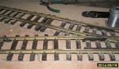
the only weak points are the turnouts and the connections, the fishplates.
you could replace them with rail-clamps (split jaw, massoth etc) all together, or only when and where one fails.
or you could solder the rails together.
or you could solder connecting pieces of wire to the rails.
or, you could make temporary makeshift fixes, like i do.
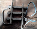
with cables, or even soldering wire just squeezed between rail and sleepers.

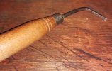
using a homemade tool:


Yes and no, how long is your line?So what you're saying is if I have ideal connectivity I may not need a bus at all
What Korm has shown will be fine indoors, but outside where oxidisation tarnishes the rail would only last a season or two.
Ok so it is worthwhile to ensure that all the track is well connected ie not just relying on the as supplied fishplates out in the garden. In time they will tarnish and reliability will be imoared. There are a few ways to resolve this, in order of my personal preferenceI have two separate shuttles. They are both 100 ft long
1 the easiest replace the fishplates with Massoth Clamps (other makes are available).
2 do soldered connections between each rail by each fishplate.
3 do regular feeds down the line say every 20 feet, this could be your bus line.
JimmyB
Now retired - trains and fishing
Similar to what
 dunnyrail
says, outside, the bond across rail connections, and not rely on standard fishplates, but I think that is the gold plated solution. Clean track end, and rail clamps (of your choice), with a little "conductive paste"* on each.
Graphite or copper paste, however, it is NOT 100% conductive, but helps prevent oxidisation of the rail.
Graphite or copper paste, however, it is NOT 100% conductive, but helps prevent oxidisation of the rail.
korm kormsen
Registered
I have two separate shuttles. They are both 100 ft long
sigh...
here we go again.
everybody knows what did work or not work for themself - and thus does not recognise different circumstances.
---
if the connectivity of your track is ok, for a single line of track (your 100ft) you probably don't need a bus.
(it depends where you feed the electricity to the track. if you feed the track at the first foot of the 100 with a cable of 1' length, one or two mm thick, and add a bus of 101ft length (even if this bus is as thick as your thumb) to the other end of the track, you gain (almost) nothing - because inside the regulator the cables are thin too, and the electricity has to travel the same distance in the bus, as in the rails.
you would gain more power at the extremes, by connecting the regulator somewhere near the 50ft midpoint of the track.
(what i don't know, is if you need one or two buses for your two lines in DCC)
if the connectivity of your track is not ok:
if you feed the track at the first foot of the 100 with a cable of 1' length, one or two mm thick, and add a bus of 101ft length to the other end of the track, you got one disconnect free (because electricity reaches from both sides to the disconnected spot)
but starting with the second disconnected spot - you'll have to start mending things.
Mr Murphy will see to it, that things don't work, just when you want to show off...
that is why i suggested to squeeze cables under the rails.
once found the spot, it takes a minute at most, to install.
(i swear on "make do" solutions)

to repeat myself, the best would be using rail-clamps before oxidation ore movements occur. depending on the lengths of track you got, you'll need one to two hundred.
the second best, IMO, would be to either solder the rails together, or the rails to the fishplates (if you can solder better, than i can)

ps: soapy water and a stiff brush work wonders.
in the early 80ies when i broke up my second layout (the only one, i had in the mud) track was treated that way.
and for my upcoming fifth layout only those with homemade connections will get that treatment again. (about a dozen from over 400ft)
Last edited:
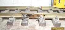
Hm ok, soldering fishplates not the best thing in the world, looks horrible and makes changes to the layout very difficult. Plus you are soldering at the largest part of the rail requiring lots of heat as witnessed by the molten chairs each side.sigh...
here we go again.
everybody knows what did work or not work for themself - and thus does not recognise different circumstances.
---
if the connectivity of your track is ok, for a single line of track (your 100ft) you probably don't need a bus.
(it depends where you feed the electricity to the track. if you feed the track at the first foot of the 100 with a cable of 1' length, one or two mm thick, and add a bus of 101ft length (even if this bus is as thick as your thumb) to the other end of the track, you gain (almost) nothing - because inside the regulator the cables are thin too.
you would gain more power at the extremes, by connecting the regulator somewhere near the 50ft midpoint of the track.
(what i don't know, is if you need one or two buses for your two lines in DCC)
if the connectivity of your track is not ok:
if you feed the track at the first foot of the 100 with a cable of 1' length, one or two mm thick, and add a bus of 101ft length to the other end of the track, you got one disconnect free (because electricity reaches from both sides to the disconnected spot)
but starting with the second disconnected spot - you'll have to start mending things.
Mr Murphy will see to it, that things don't work, just when you want to show off...
that is why i suggested to squeeze cables under the rails.
(i swear on "make do" solutions)
View attachment 347231
to repeat myself, the best would be using rail-clamps before oxidation ore movements occur. depending on the lengths of track you got, you'll need one to two hundred.
the second best, IMO, would be to either solder the rails together, or the rails to the fishplates (if you can solder better, than i can)
View attachment 347232
ps: soapy water and a stiff brush work wonders.
in the early 80ies when i broke up my second layout (the only one, i had in the mud) track was treated that way.
and for my upcoming fifth layout only those with homemade connections will get that treatment again. (about a dozen from over 400ft)
Far better if you are going to solder is to use jumper wires (black insulated wire please) then solder to the rail webb, here there is less metal and thus less heat required for a soldered joint and less damage to the very expensive track. Leaving a small extra of wire allows for some movement in changes of weather & heat.
