Does anyone know if it's possible to use the Massoth/LGB train detection & feedback modules* with a PIKO system WITHOUT a PC interface
Yes, both Massoth and MD Electronics train detection modules will be fine, but not LGB's offering, wrong Bus connector and protocol, Massoth feedback module 8170001 obviously will work.
*The LGB 55070 feedback module, can be used as a Slave Unit, with limitations, it will however work with Reed, Hall Sensors and Train Detection methods, although it is a bit of a one way way street if designing multiple Automatic Routines, will eventually end up in a cul-de-sac with nowhere to go, expensive frustrating mistake to correct, best avoid using the LGB 55070.
Design any Automatic system, (Autonomous or Semi Autonomous hardware routines that can be operated in conjunction with) around the Massoth 817001, which incidentally I've never got a straight answer from Massoth, as to whether it was by accident or design, that by the nature of being able to manipulate the values for the CV's that make the Feedback module function, it is possible to attach DIY Home Brew, non Massoth certified Sensors and Detectors to function and operate alongside genuine Massoth equipment.
PC Interface is irrelevant, there isn't one!
Basically, I'd like to do a few automatic signal/switch throws with reed switches and detection modules, but not sure if the basic PIKO central station / navigator alone would allow me to do that. I'm still new to DCC and not quite in for getting a PC interface set up yet.
Yes that is workable, although the PIKO CS has some limitations:
a) No central resource to save the Automatic routines too, where as the Massoth CS has the ability to save these amongst a plethora of other data.
If multiple Navigators are in use, routines will have to be manually input to each one, Automatic routines are saved locally to the Navigator either PIKO or Massoth.
b) PIKO CS is unable to report or monitor feedback from Sensors or Detectors, even if the Navigator handsets have the Special Mode configured and active.
Depending on the simplicity or complexity of the Automatic routines, they can be monitored externally by using an Arduino with a DCC receiver interface connected to the PIKO system, on screen real time data can be viewed to verify correct operation of the Automatic routines.
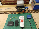
Below picture of basic minimum equipment required, the two Reed switches, control an Automatic Switch routine to operate the LGB point motor Normal or Thrown, plus they also control the Automatic Drive routine that sends instructions to the drive decoder, to go forward, stop, wait, continue in same direction, delay, reverse direction, etc, etc.
Oh! and on any purchase list include for, and purchase a Massoth 8138001 Bus Adapter, the PIKO CS is only blessed with one single output port!
View attachment 270034
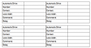
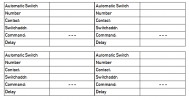
To assist with designing Automatic routines, using Writer from Libre Office created tables to keep track of what does what, bear in mind a basic system can handle a total of 32 inputs, 16 'A' type ports, and 16 'B' type ports.
View attachment 270041
View attachment 270042


