Any idea what I can now use this board for

dunnyrail

DOGS, Garden Railways, Steam Trains, Jive Dancing,
Staff member
GSC Moderator
Country flag
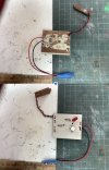
I got this in the long ago mists of time and presumably stripped it out as things were not working. Somewhere a sensor has gone missing but nothing occurs when one puts a battery on and short the two wires on the sensor board. Any adeas what it could be useful for now or should I just strip out the components and put them in my bits boxes?
B40DBFCF-CF9E-41FA-9D18-158DBA3C7586.jpeg
 
Whatever it is, it's home made.

The PCB is obviously self etched....
 
It could be a battery detector!

Plug a good battery in....no light = battery not missing
Plug a dead battery in....no light = battery not missing

Seriously..could have once been a light detector.....for hidden sidings etc
shorting the two sensor wires could have turned the led on....

the only useful thing for your spares bucket could be the battery connector

Malcolm
Well I can test out the LED, the resisters should be ok and that sikverything that has 3 wires out to be something?
 
Best guess, would be as an 'amplifier' to boost the weak input signal from the Sensor, to trigger the LED to turn on.

A closer or close up of the rear of the PCB might help to trace out the 'input' and 'output'..... probably more for an academic curiosity point of view for yourself, as to what it does, or what it did.
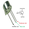
Ok so the Transistor has CDIL BFY51 on it with E6 as well printed the other way. Emitter has the little blip as per your diagram so this is going to the neg (black) of the battery lead. Collector appears to be connected to the Live (flat dimple side) of the Led. Base is connected via a resister to the red of the Vero Board. Curiously the Red from the Battery is connected to the bkack on the vero board. I wonder who RJK was who designed it, guess we will never know. Many thanks for the ideas and interest.
 
Last edited:
Ok so the Transistor has CDIL BFY51 on it with E6 as well printed the other way. Emitter has the little blip as per your diagram so this is going to the neg (bkack) of the battery lead. Collector appears to be connected to the Live (flat dimple side) of the Led. Base is connected via a resister to the red of the Vero Board. Curiously the Red from the Battery is connected to the bkack on the vero board. I wonder who RJK was who designed it, guess we will never know. Many thanks for the ideas and interest.

My best guess is probably the transistor (BFY51 is an NPN medium power transistors in a TO-39 package designed for general purpose industrial applications. ) is wired as a switch which turned on the LED when the Base level changed.
Change the base signal level to Base +ve With Respect To (WRT) the Emitter and the transistor (in NPN opposite in PNP) is turned on and current flows (it conducts) through the LED turning it on.
Change the base signal to the opposite signal level and the transistor turns off and LED goes out no current flow.
A Reed switch reacting to a magnet or a Light Dependent Resistor (LDR) reacting to reduced light levels are 2 possible devices that could be used to change the Transistor Base level.
 
Thinking further on the circuit it could be used for signal or points position indications, a microswitch used to turn on and off the transistor (switch), with the transistor off a LED is lit and when on another LED is lit and the first one is bypassed turning it off.
Now you have me thinking about how I could do that on my layout with the microswitch activated by the point throw bar, sending the output to a mimic panel.
Thanks for reminding me.
 
There's a well known RJK electronic company that makes burglar alarms, it could be something they made
Oh now there is a possibility, have pulled out the odd very old Burgler Alarm that was going off with no way to stop them it. Me being me would likely take out a board with bits that looked interesting so that could be the answer. But the truth will remain locked in that black hole that I call a brain.
 
Back
Top Bottom