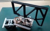
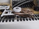
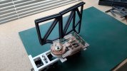
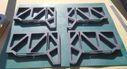
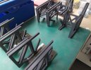
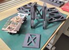
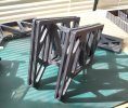
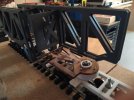
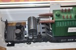
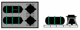
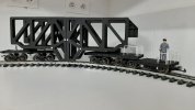
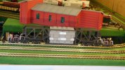
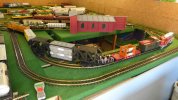
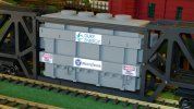
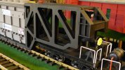
3D power transformer printing and associated transport wagon

Zerogee

Clencher's Bogleman
25 Oct 2009
17,351
1,723
North Essex
Best answers
0
Country flag
Thank you for your post Jon.

With your eagle eyes you have seen someting I did not noticed !
Even I don't understand what it means !!

Does this mean in other words : do not bump ! ... ?

Sorry, just my immature and childish (ie: British) sense of humour....! :rofl:

The sign actually means that the wagon is not to be "hump shunted", which is a form of gravity shunting: Classification yard - Wikipedia

But "hump" can have another, slightly rude meaning to English speakers (something that two people do, or a male dog does to someone's leg), hence finding the sign funny.... :devil:

Jon.
 
  • Like
  • Wow
Reactions: 1 users

ARIA31

Registered
3 Oct 2017
250
54
74
Toulouse - France
Best answers
0
Country flag
As announced there is some fun with the manufacturing of required parts..... !! :D

Have a look at this video .:)


Yes this is still modelling as 3D printing is.
 
  • Like
Reactions: 1 user

ARIA31

Registered
3 Oct 2017
250
54
74
Toulouse - France
Best answers
0
Country flag
As stated before, the rolling tests shown the detrimental effects of free plays in the 2 bogies assembly.

Accordingly special care was put in the fulcrum design and ball bearings are widely used.

The screws connecting each bogie to the common chassis are installed with a ball bearing at the chassis level.

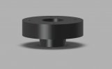
Then for the fulcrum a large cylinder is created to counter act the base plate rocking sidewise.
1602160937602.jpeg

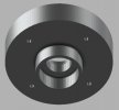
This large cylinder is fitted with 2 ball bearings around the fulcrum screw and is installed on the common chassis (one ball bearing at the top, one ball bearing at the bottom).
pivot 4.JPG

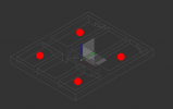
The base plate has been machined ( see video of the previous post ) as per the following 3D design.
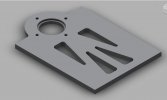
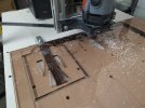
w1.JPG


IMG_20200429_144145.jpg

When assembled with the cylinder we get this :
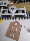
IMG_20200429_202130.jpg

IMG_20200430_111725.jpg

IMG_20200430_111734.jpg

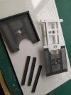
Now we have to create the 8 ribs ( twice four for each chassis ) which will be fixed onto the base plate.

Joël started to machine the ribs with the same material as the one used for the base plate ( plexiglas) but it appeared this is more difficult and also very long lasting. (several hours of machining per rib). So we looked for different material.

At the end, Joël decided to evaluate if these parts might be done with 3D printing.
So he created a new 3D file and started the printing.

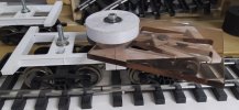
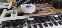
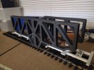
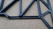
The result is quite promising and the assembly of the 4 ribs onto the base plate much easier than with the previous design and parts acquisition.
However for the complete wagon 24 printing hours are required for the 8 ribs !!
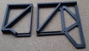
20201006_171349.jpg

When assembled

20201006_171402.jpg

The following picture shows the slot which allows this rib to be connected to the base plate side
20201006_171408.jpg

Like that:

20201006_171012.jpg

20201006_170917.jpg

Then an inner rib will close this complete rib assembly.

This is where we are today.

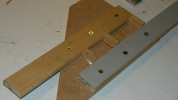
The next major assembly of the wagon will be the cradle placed in between the 2 half wagons and carrying the transformer. The design is currently underway. It will be made of 3D printed parts as well, but being quite long, reinforced with 2 aluminium U shaped rails.

Later on we intend to put details features (cabinet, hand rail, pumps,... etc) on this skeleton to make it more real.
 

Attachments

  • IMG_20200430_111725.jpg
    IMG_20200430_111725.jpg
    144 KB · Views: 0
  • 20201006_171012.jpg
    20201006_171012.jpg
    382.1 KB · Views: 0
  • Like
Reactions: 1 user

ARIA31

Registered
3 Oct 2017
250
54
74
Toulouse - France
Best answers
0
Country flag
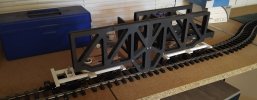
Progress is made by gluing the ribs onto the chassis

temp(27).jpg


temp(29).jpg

temp(32).jpg

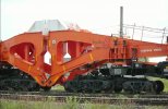
this configurationn occurs when the heavy load has been delivered as on following pictures

maxresdefault.jpg
 
  • Like
Reactions: 1 user

ARIA31

Registered
3 Oct 2017
250
54
74
Toulouse - France
Best answers
0
Country flag
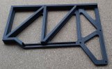
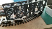
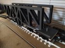
3D printing is going on. the 4 ribs are now available

20201021_165216.jpg

We are keen to get the wagon rolling on a railroad

20201021_171803.jpg

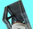
We are looking for the grids.
From below:

20201021_170024 - 1.jpg

20201021_165254.jpg
The cradle design is now underway. 2 aluminium rails are forecasted for re-inforcement.
My friend is considering a machining process to get it as shown in post 22.
 

Attachments

  • 20201021_165254.jpg
    20201021_165254.jpg
    490.8 KB · Views: 0
  • Like
Reactions: 1 user

ARIA31

Registered
3 Oct 2017
250
54
74
Toulouse - France
Best answers
0
Country flag
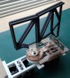
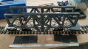
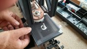
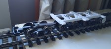
After some trade-off the grids design is frozen with some reinforcements and printing started.

temp(40).jpg

temp(45).jpg

The white chassis will be painted black.

On the last pict you can notice the white rails that my friend printed as well :D

Then we decide to increase the length of this wagon by adding another bogie on each side leading the wagon be now a 6 bogies assembly !!

The first issue is to link the added bogie to the other ones. Accordingly , a special rod is designed and printed.

temp(42).jpg
 

Attachments

  • temp(42).jpg
    temp(42).jpg
    696.9 KB · Views: 0
  • Like
Reactions: 1 user

mike

Master at annoying..
Staff member
GSC Moderator
24 Oct 2009
51,806
4,435
Rossendale
www.gscalecentral.net
Best answers
0
Country flag
Wow
 

ARIA31

Registered
3 Oct 2017
250
54
74
Toulouse - France
Best answers
0
Country flag
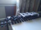
We made some progress on this wagon construction.

It is time now for a first rolling test on my railroad which is R1 evrywhere.
We had some concern about hook and loop coupling between a GP38-2 that will be used to drive the future consist and the first small car. (We call it additional wagon)

Here is a video of this first test run.


We concluded that some weight must be added on the additional wagon. (250 grams)
 

JGDURAND

Registered
28 Aug 2013
188
241
Chatellerault France
Best answers
0
Country flag
Impressionnant, bravo
 

ARIA31

Registered
3 Oct 2017
250
54
74
Toulouse - France
Best answers
0
Country flag
The wagon next steps are :
a) the craddle design and manufacturing,
b) the supplemental braking system installation on the 2 additional wagons
c) all additionnal details

For the supplemental braking system I decided to step away a little bit from the initial design guideline (the MTH schnabel car-see post 13)
and look at the LGB transformer wagon PN 4058 braking.

bbbbb.jpg

However I did not understood how it works, so I placed a question on this forum and got an immediate response ( thank you TonyMP52)

and with my friend Joël this is what we will implement on the additional wagon. The draft is as follows:

wagon sup freinage.jpg

As said before , we need to add some weight on this car .
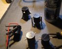
We are considering to take benefit of the reservoirs to hide the lead or steel weight.

The craddle will add around 25 cm and at the end the complete wagon will be around 115 cm long.

You possibly noticed the white barriers.
They are made with a 1 mm diameter rod slid into a 2 mm sheath., that can be found both in radio controlled airplane shop.
For sure a small tooling muust be created to bend the rod.

20201213_162009.jpg
 

ARIA31

Registered
3 Oct 2017
250
54
74
Toulouse - France
Best answers
0
Country flag
The two additional wagons, the front one and the rear one, turned out to be a little light and sometimes derailed.

I did some tests with a weight of 200 grams per wagon and it works much better.

The frame designed and produced in 3D by my friend has 4 locations to install lead weights.

1615999931125.png

I made a wooden mold to obtain ingots roughly the size I wanted, providing a handle to hold the "mold".

1616000029599.png

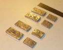
Then I melted the 8 weights with lead using my portable C Gas torch.


1616000127326.png

Despite the color they are not made of gold .....:)

Although the thicknesses are quite variable, I have two batches of very close mass: 260 and 290 grams.

As we forgotten the space neede for the wheels, it was necessary to machine the 4 weights to allow them to be inserted in the chassis.

1616000388337.png
 

ARIA31

Registered
3 Oct 2017
250
54
74
Toulouse - France
Best answers
0
Country flag
The additional braking system has been printed

img_2128.jpg

IMG_20210328_182659.jpg

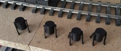
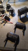
The reservoirs as well

IMG_20210330_213651.jpg

Then everything is installe don the wagons

IMG_20210330_224534.jpg

For "safety reasons" ;) we are adding manual brakes

part000001(7).jpg

part000001(3).jpg
 

ARIA31

Registered
3 Oct 2017
250
54
74
Toulouse - France
Best answers
0
Country flag
As the new schnabel car might require 2 diesel engines to move it , the South West Indoor Railroad procured a new USA trains Gp9.
As I am not familiar to drive two engines on the same railroad I tested my hability to do it with my DC control.
Here is a video I made several weeks ago:


Now the schnabel car is shipped to my railroad with a dedicated casing due to the length.
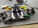
1619524382858.png

The beast has indeed arrived and is circulating very well on my circuit. (not everywhere !!)


The railroad has been modified (no more tunnel, no more station, .... etc) ... !!

1619524581760.jpeg


1619524619241.jpeg

1619524654482.jpeg

1619524672807.jpeg


1619524687237.jpeg
 
  • Like
Reactions: 1 user

ARIA31

Registered
3 Oct 2017
250
54
74
Toulouse - France
Best answers
0
Country flag
EPILOGUE :
This month MRH includes an article about this Schnabel Car .
This article is included into the Running Extra part.
It includes most of what is on this thread.

MRH front page.png
 
  • Like
Reactions: 1 user